


Item
Name
Icon
Description
1
Optional cable
retention positions
(4)
—
Locations for optional cable retention brackets.
2
Expansion
Enclosure Modules
(2)
—
Each EMM contains SAS ports and status indicators.
3
Cooling fans (5)
—
Fans that provide cooling for the expansion enclosure.
4
Power supply units
(2)
—
2.8 kW power supply that provides power for the expansion
enclosure.
5
Optional cable
retention positions
(4)
—
Locations for optional cable retention brackets.
6
Power switch (2)
—
Controls power for the expansion enclosure. There is one
switch for each power supply.
SC180 Expansion Enclosure EMM Features and Indicators
An SC180 expansion enclosure includes two Enclosure Management Modules (EMMs) in two Storage
Bridge Bay (SBB) interface slots.
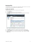
Figure 3. SC180 EMM Features and Indicators
Item
Control/
Feature
Icon
Description
1
Fault LED
•
Off
— Module OK
•
Amber
— Module fault
2
Power LED
•
Green
(steady) — Module OK
•
Green
(flashing) — Vital product data (VPD) fault
•
Off
: Module fault
3
Console port
Not for customer use.
4
SAS ports
Connect to the storage system
10
About the SC180 Expansion Enclosure


