background image

Power supplies

The S6100–ON supports AC or DC power supplies with two air-flow directions, normal and reverse. Normal airflow is from the I/O to the 
PSU and reverse airflow is from the PSU to the I/O.
Two PSUs are required for full redundancy, but the system can operate with a single PSU. To protect against high-voltage shock, install a 
power supply blank in all unused power supply slots.

The PSU is field replaceable. When running with full redundancy—two power supplies installed and running, you can remove and replace 
one PSU without disrupting traffic.

CAUTION: 

To prevent electrical shock, ensure that the S6100-ON is grounded properly. If you do not ground your equipment 

correctly, excessive emissions may result. Use a qualified electrician to ensure that the power cables meet your local electrical 
requirements.

NOTE: 

Connect the power supply to the appropriate branch circuit protection as defined by your local electrical codes. Verify 

that the remote power source complies with the system input power specifications.

NOTE: 

ESD damage can occur if components are mishandled. Always wear an ESD-preventive wrist or heel ground strap when 

handling the S6100–ON and its components.


Topics:

Components

AC or DC power supply installation

AC or DC power supply replacement

Components

The following power supply options are available for the S6100–ON:

AC or DC power supply with integrated fan

AC or DC power supply with integrated reverse flow fan

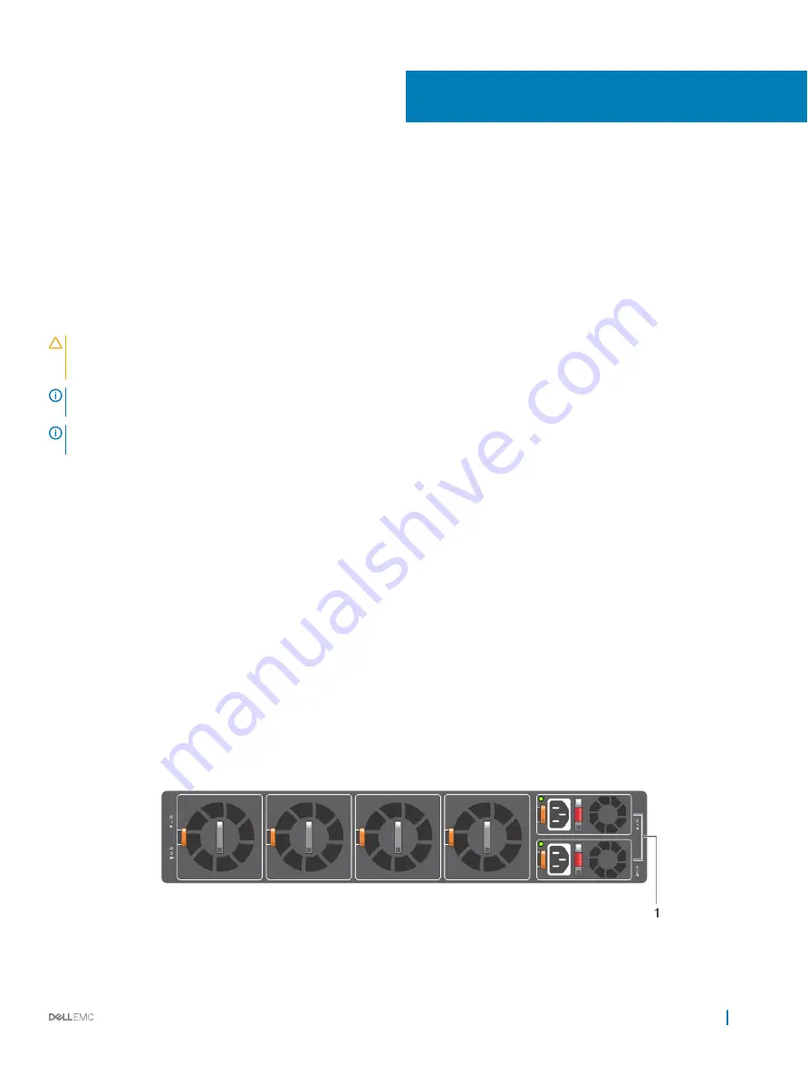
Both PSUs are on the right side of the switch. Power supply 1, 

PSU1

, is on the top of the chassis; power supply 2, 

PSU2

, is on the bottom 

of the chassis.

Figure 24. S6100–ON PSUs

6

Power supplies

33

Содержание S6100

Страница 1: ...Dell Installation Guide for the S6100 ON System June 2017 ...

Страница 2: ...e to hardware or loss of data and tells you how to avoid the problem WARNING A WARNING indicates a potential for property damage personal injury or death Copyright 2017 Dell Inc or its subsidiaries All rights reserved Dell EMC and other trademarks are trademarks of Dell Inc or its subsidiaries Other trademarks may be trademarks of their respective owners 2017 06 Rev A04 ...

Страница 3: ... and airflow 14 Fan combinations 14 Power 14 Storing components 15 4 NEBS compliance 16 Important information 16 NEBS compliant ground installation 16 For rack spans from 22 to 23 375 inches 17 For rack spans from 23 375 to 36 inches 19 5 S6100 ON installation 23 Installation overview 23 Unpack the S6100 ON System 23 Four post rack assembly 24 Four post rack mount 24 Chassis ground 25 I O module i...

Страница 4: ...ore you install an OS 44 Grub bootloader exampleONIE example 45 ONIE service discovery 45 9 Dell support 47 10 Specifications 49 Chassis physical design 49 IEEE standards 50 Agency compliance 51 USA Federal Communications Commission FCC statement 51 European Union EMC Directive Conformance statement 51 Japan VCCI Compliance for Class A Equipment 52 Korean Certification of Compliance 52 Safety Stan...

Страница 5: ...optical transceivers which comply with the limits of Class 1 laser radiation Figure 1 Class 1 Laser Product Tag WARNING When no cable is connected visible and invisible laser radiation may be emitted from the aperture of the optical transceiver ports Avoid exposure to laser radiation and do not stare into open apertures Related documents For more information about the S6100 ON system see the follo...

Страница 6: ...S6100 ON system includes two hot swappable AC or DC power supply units PSUs and four hot swappable fan units The S6100 ON supports three types of I O modules 16 x 40 GbE QSFP Top row of ports can operate as Single 40G port Quad 10G ports NOTE If you configure port n as a quad 10G port port n 1 will not be available 8 x 100 GbE QSFP28 Each port can operate as Single 100G port Single 40G port Quad 2...

Страница 7: ...10 40 GbE QSFP ports Up to four I O modules of 4 x 10 25 40 50 100 GbE QSFP28 ports and 4 x 100 GbE CXP ports Up to one hundred twenty eight 10G ports Up to one hundred twenty eight 25G ports Up to sixty four 40G ports Up to sixty four 50G ports Up to thirty two 100G ports Two SFP ports One micro universal serial bus MicroUSB B console port optional One 2 0 USB Type A port for additional file stor...

Страница 8: ...dard 2U chassis Two hole ground lug Physical dimensions The S6100 ON has the following physical dimensions 442 x 510 x 86 75 mm W x D x H 17 40 x 20 x 3 41 inches W x D x H Luggage tag The S6100 ON system has a pull out tag known as a luggage tag on the I O side of the system Figure 4 S6100 ON luggage tag 1 Service tag 2 PPID 8 S6100 ON system ...

Страница 9: ...LED behavior The following S6100 ON system LED behavior is seen during open networking installation environment ONIE operations Figure 5 S6100 ON LEDs 1 Fan LED 2 Power LED 3 Master LED 4 System LED 5 Locator LED 6 Locator LED 7 System LED 8 Port LEDs 9 Stack ID LED 10 RJ 45 Ethernet Management Port LED Table 1 S6100 ON LED behavior LED Description System Status and Health LED Off No power Solid g...

Страница 10: ...luding incompatible airflow direction when you insert the PSU or fan trays with differing airflows LOCATOR LED Off Locator is idle Blinking blue Locator is functioning Table 2 QSFP28 port LEDs LED Description Link LED Off No Link Solid green Port activity operating at maximum port speed Solid amber Port activity operating at lower speed Activity LED Off No Link Flashing green 30 ms port activity o...

Страница 11: ...ower port speed Prerequisites The following is a list of components required for successful installation of the S6100 ON NOTE Detailed installation instructions for the S6100 ON are provided in Site preparations and S6100 ON Installation S6100 ON chassis or multiple chassis if stacking AC or DC country and regional specific cables to connect the AC or DC power source to each of the chassis AC or D...

Страница 12: ... thirty two 10 25 40 100 GbE ports with four SFP 10 GbE ports two AC or DC power supply units and four fan subsystems Fan airflow is from the I O side to the power supply side Fan with airflow from the I O side to the PSU side Fan with airflow from the PSU side to the I O side AC or DC power supply with airflow from the I O side to the PSU side AC or DC power supply with airflow from the PSU side ...

Страница 13: ...sure that the area where you install your S6100 ON system meets the following safety requirements Near an adequate power source Connect the system to the appropriate branch circuit protection as defined by your local electrical codes Environmental temperature range is from 32 to 113 F from 0 to 45 C The switch operating ambient temperature range is from 10 to 35 C from 50 to 95 F Relative humidity...

Страница 14: ...everse and normal airflows in a single S6100 ON chassis For proper ventilation position the S6100 ON in an equipment rack or cabinet with a minimum of 5 inches 12 7 cm of clearance around the exhaust vents When you install two S6100 ON systems near each other to permit proper airflow position the two chassis at least 5 inches 12 7 cm apart The fan speed increases when the internal temperature reac...

Страница 15: ...from 40 to 158 F 40 C to 70 C Store on a dry surface or floor away from direct sunlight heat and air conditioning ducts Store in a dust free environment NOTE ESD damage can occur when components are mishandled Always wear an ESD preventive wrist or heel ground strap when handling the S6100 ON and its accessories After you remove the original packaging place the S6100 ON and its components on an an...

Страница 16: ...cess area were only trained personnel are allowed access Install and connect your system to the common bonding network CBN You can also install and connect your system to the central office Connect the battery returns of your system as DC I Ground your system using a copper ground conductor Clean all bare grounding connection points on your chassis and the bracket with an anti oxidant solution bef...

Страница 17: ...your local electrical codes in size and color Wires are typically green or green with a yellow stripe 2 Attach the ground lug to the mounting bracket using two M5 nuts included Torque to 30 in lb Figure 7 Switch with ground lug NOTE For proper ventilation position the chassis in an equipment rack or cabinet with a minimum of 5 inches 12 7 cm of clearance around exhaust vents The acceptable ambient...

Страница 18: ...s to rack front view Figure 9 Rack rails installed 4 Insert the chassis into the rack from the front Secure the chassis with captive screws and two additional rack screws on each side of the front of the rack Rack rail screws are not included 18 NEBS compliance ...

Страница 19: ...h the ground lug using these steps Figure 11 Switch without ground lug 1 Remove the ground lug from the shipping bag and crimp the ground wire to the lug The ground wire is not included NOTE The grounding cable must comply with your local electrical codes in size and color Wires are typically green or green with a yellow stripe 2 Attach the ground lug to the mounting bracket using two M5 nuts incl...

Страница 20: ...s 12 7 cm of clearance around exhaust vents The acceptable ambient temperature ranges are listed in the Environmental Parameters section 3 Attach the rack rails to the rack using four screws on the front of the rack and eight screws on the back of the rack Rack rail screws are not included Figure 13 Rack rails rear view 20 NEBS compliance ...

Страница 21: ...iew Figure 15 Rack rails installed 4 Insert the chassis into the rack from the front Secure the chassis with captive screws and two additional rack screws on each side of the front of the rack Rack rail screws are not included NEBS compliance 21 ...

Страница 22: ...Figure 16 Secure chassis in rack 5 Attach the other end of the ground wire to the nearest appropriate facility grounding post 22 NEBS compliance ...

Страница 23: ...ents are mishandled Always wear an ESD preventive wrist or heel ground strap when handling the S6100 ON and its components As with all electrical devices of this type take all the necessary safety precautions to prevent injury when installing this system Unpack the S6100 ON System Before unpacking the system inspect the container and immediately report any evidence of damage Verify that you have r...

Страница 24: ... top Be sure that the heaviest component is at the bottom of the rack If the rack comes with stabilizing devices install the stabilizers before mounting or servicing the unit in the rack If the chassis ships with blanks remove the blanks from each slot before lifting the chassis WARNING These instructions are a condensed reference Read the safety instructions in your Safety Environmental and Regul...

Страница 25: ...S6100 ON system installation 1 Extra screws to restrict front back movement of the switch 2 Main screw Chassis ground After you mount the chassis secure the chassis ground as follows To properly ground the chassis Dell recommends using the two hole lug shipped in a separate plastic bag with your chassis The two hole lug must be a UL recognized crimp type lug To connect the ground cable to the fram...

Страница 26: ...tor 1 Ground cable 2 Two hole chassis ground connector 2 Install the grounding cables to the ground nuts The grounding cable must comply with your local electrical codes in size and color Wires are typically green or green with a yellow stripe NOTE For proper ventilation position the chassis in an equipment rack or cabinet with a minimum of 5 inches 12 7 cm of clearance around exhaust vents The ac...

Страница 27: ...rows located inside the chassis and then gently slide the I O module in place 1 Remove the I O module from the electro static bag 2 Open the left ejector lever item 1 by pressing in the orange tab item 2 and rotating it to the right The level snaps into the open position 3 Slide the I O module into the switch I O slot The slot is keyed so that the I O module fully inserts in only one way When you ...

Страница 28: ...e S6100 ON does not support mixing PSU types The fan airflow direction for the PSUs must be the same Module power is software controlled You do not see module LEDs when the system powers up CAUTION DO NOT mix airflow directions Both power supplies must use the same airflow direction I O to PSU or PSU to I O WARNING Although the switch can run on one PSU Dell highly recommends using two PSUs for fu...

Страница 29: ...e optic and sliding the optic from the port CAUTION When removing optics with direct attach cables DACs from the port pull the release tab firmly and steadily If you have difficulties pulling out the cable gently push the optic into the port with one hand and at the same time pull the release tab slightly upwards towards the cable or module center with the other hand Do not jerk or tug repeatedly ...

Страница 30: ... 4 8 0 red 1 9 1 10 1 11 1 12 2 5 2 6 2 7 2 8 3 13 3 14 3 15 3 16 4 9 4 10 4 11 4 12 1 orange 1 5 1 6 1 7 1 8 2 9 2 10 2 11 2 12 3 9 3 10 3 11 3 12 4 13 4 14 4 15 4 16 2 green 1 1 1 2 1 3 1 4 2 13 2 14 2 15 2 16 3 5 3 6 3 7 3 8 4 1 4 2 4 3 4 4 3 blue Figure 22 16 x 40G module port pipes Table 8 Port and port pipe distribution 4 x CXP 4 x QSFP28 modules Slot Port Port pipe 1 7 1 8 2 1 2 2 3 1 3 2 4...

Страница 31: ...Do not power up the switch if you did not install a fan module NOTE A US AC or DC power cable is included for powering up an AC or DC power supply You must order all other power cables separately NOTE ESD damage can occur if components are mishandled Always wear an ESD preventive wrist or heel ground strap when handling the S6100 ON system and its components Power up sequence When the system power...

Страница 32: ...NOTE Module power is software controlled You do not see module LEDs when the system powers up in ONIE 32 S6100 ON installation ...

Страница 33: ...se a qualified electrician to ensure that the power cables meet your local electrical requirements NOTE Connect the power supply to the appropriate branch circuit protection as defined by your local electrical codes Verify that the remote power source complies with the system input power specifications NOTE ESD damage can occur if components are mishandled Always wear an ESD preventive wrist or he...

Страница 34: ...ipment Interfacing with AC Power Ports use an external surge protection device SPD at the AC input of the router AC or DC power supply installation NOTE The PSU slides into the slot smoothly Do not force a PSU into a slot as this action may damage the PSU or the S6100 ON chassis NOTE Ensure that you correctly install the PSU When you install the PSU correctly the power connector is on the right si...

Страница 35: ...witch PSU to the external power source 5 Repeat steps 1 through 4 above using the second PSU slot on the S6100 ON system NOTE The S6100 ON powers up when the cables are connected between the power supply and the power source DC power supply connection Each DC powered system comes with a set containing a prewired 3 inch 8 AWG power supply connector and a four screw wiring block One set is provided ...

Страница 36: ...Figure 27 DC power connector ground 1 Ground nut 2 Washer 3 Lock washer 4 Ground cable 5 Device grounding rod 1 Strip 1 2 inches of insulation from each of the power connector s red and black wires as shown 2 Insert each of the power connector s bare wire lengths into the wiring block Insert red into one hole and black into the other hole as shown 36 Power supplies ...

Страница 37: ...ctor s clamps While continuing to squeeze pull the power connector from the DC PSU socket AC or DC power supply replacement CAUTION Disconnect the power cord before removing the power supplies Also disconnect all power cords before servicing NOTE The PSU slides into the slot smoothly Do not force a PSU into a slot as this action may damage the PSU or the S6100 ON chassis NOTE If a PSU fails you mu...

Страница 38: ...ow Normal airflow is from the I O panel to the PSU red Reversed airflow is from the PSU to the I O panel blue All fans and PSUs in a configuration must be in the same airflow direction Environmental factors can decrease the amount of time required between fan replacements Check the environmental factors regularly An increase in temperature and particulate matter in the air might affect performance...

Страница 39: ...assis CAUTION DO NOT mix airflow directions All fans must use the same airflow direction reverse or normal If you mix the airflow direction the switch detects the discrepancy issues an alarm and may auto shutdown to avoid heat damage to components You must correct the mixed airflow direction 1 Take the fan module out of the shipping box 2 Use the grab handle and the orange tab to slide the module ...

Страница 40: ...ase in temperature and or particulate matter in the air might affect performance CAUTION Check the fan air filters at six month intervals and replace them as necessary To accurately determine air filter replacement intervals regularly monitor the speeds of the cooling fans An increase in overall fan speed may indicate a clogged filter You must replace the fan air filters with new filters you canno...

Страница 41: ...quired 1 Determine which filters to replace 2 Unlatch and remove the first module that needs the filter replaced 3 Slide the existing filter upwards to remove it from the module 4 Replace the filter with a new filter of the same size 5 Repeat for the remaining modules that need the filter replaced After system installation After you have securely installed and powered on the S6100 ON to configure ...

Страница 42: ...d to the serial port can support the required 115200 baud rate NOTE Be sure that your PC has a 9 pin serial port and that you have a terminal emulation program already installed and running on the PC NOTE If your PC s serial port cannot accept a female DB 9 connector acquire a DB 9 male to male adaptor 1 Install the provided RJ 45 connector side of the provided cable into the S6100 ON console port...

Страница 43: ...5 console port 115200 baud rate No parity 8 data bits 1 stop bit No flow control When you connect the micro USB B port it becomes the primary connection and while connected all messages are sent to the micro USB B port NOTE Before starting this procedure be sure that you have a terminal emulation program already installed on your PC Install the appropriate drivers to support the micro USB B port F...

Страница 44: ... mounting dev sdb on mnt usb failed No such file or directory NOTE The following message displays if the USB device is not seen mount mounting dev sdb on mnt usb failed No such device or address 4 Add a device to the file systems table fstab and mount the file systems ONIE vi etc fstab FSTAB entry for the ONIE BOOT partition mounted on boot LABEL ONIE BOOT mnt onie boot ext4 defaults rw errors rem...

Страница 45: ... the initial setup the system boots to ONIE Install ONIE Install boots with ONIE Discovery to the console ONIE ONIE service discovery ONIE attempts to locate the installer through several discovery methods as shown To download and run an installer the ONIE Service Discovery feature uses the first successful method found 1 Pass from the boot loader 2 Search locally attached storage devices for one ...

Страница 46: ... Scope Link UP BROADCAST RUNNING MULTICAST MTU 1500 Metric 1 RX packets 18 errors 0 dropped 0 overruns 0 frame 0 TX packets 24 errors 0 dropped 0 overruns 0 carrier 0 collisions 0 txqueuelen 1000 RX bytes 1152 1 1 KiB TX bytes 6864 6 7 KiB Interrupt 21 Memory ff300000 ff320000 To assign an IP address to the management interface eth0 and verify network connectivity use the ifconfig eth0 ip address ...

Страница 47: ... and select your country from the drop down menu To obtain product specific information enter the 7 character service tag known as a luggage tag or 11 digit express service code of your switch and click Submit To view the chassis service tag or express service code pull out the tag or enter the show chassis command from the CLI The service tag is one the I O side bottom left of the system To recei...

Страница 48: ...Figure 31 S6100 ON luggage tag 1 Service tag 2 PPID 3 MAC address 4 Express service code 48 Dell support ...

Страница 49: ... VCCI Compliance for Class A Equipment Korean Certification of Compliance Safety Standards and Compliance Agency Certifications Electromagnetic Compatibility EMC Product recycling and disposal Chassis physical design Table 10 Chassis physical design Parameter Specifications Height 3 50 inches 88 9 mm Width 17 1 inches 434 3 mm Depth 18 inches 457 2 mm Chassis Weight with Factory Installed Componen...

Страница 50: ... MTBF 1 154 397 hours Table 13 DC power requirements Parameter Specifications PSU Maximum Power Capability 1100 Watts PSU Maximum current required 32A Minimum and maximum input voltage range 40 5 V 48 V 60 V Input power at full load 40 5 V 970 W 48 V 930 W 60 V 950 W without fan 40 5 V 980 W 48 V 940 W 60V 960 W with fan Input current at full load 40 5V 23 8A 48V 19 0A 60V 15 6A without fan 40 5V ...

Страница 51: ...ority to operate the equipment This device complies with Part 15 of the FCC Rules Operation is subject to the following two conditions 1 this device may not cause harmful interference and 2 this device must accept any interference received including interference that may cause undesired operation Figure 32 Canadian Department of Communication statement European Union EMC Directive Conformance stat...

Страница 52: ...terference by Information Technology Equipment VCCI If this equipment is used in a domestic environment radio disturbance may arise When such trouble occurs the user may be required to take corrective actions WARNING Use the AC power cords with Dell Networking equipment only Do not use Dell Force10 AC power cords with any unauthorized hardware Figure 34 Japan Warning Label Korean Certification of ...

Страница 53: ...Fibre Communication Systems FDA Regulation 21CFR 1040 10 and 1040 11 IEC 60950 1 2nd Ed including all National Deviations and Group Differences Electromagnetic Compatibility EMC Emissions International CISPR 22 2006 Class A Australia New Zealand AS NZS CISPR 22 2009 Class A Canada ICES 003 Issue 4 Class A Europe EN55022 2006 CISPR 22 2006 Class A Japan VCCI V 3 2011 04 Class A USA FCC CFR47 Part 1...

Страница 54: ...as applicable throughout the European Union This label is applied to various products to indicate that the product is not to be thrown away but rather reclaimed upon end of life per this Directive Figure 37 The European WEEE symbol In accordance with the European WEEE Directive electrical and electronic equipment EEE is to be collected separately and to be reused recycled or recovered at end of li...

Отзывы: