background image

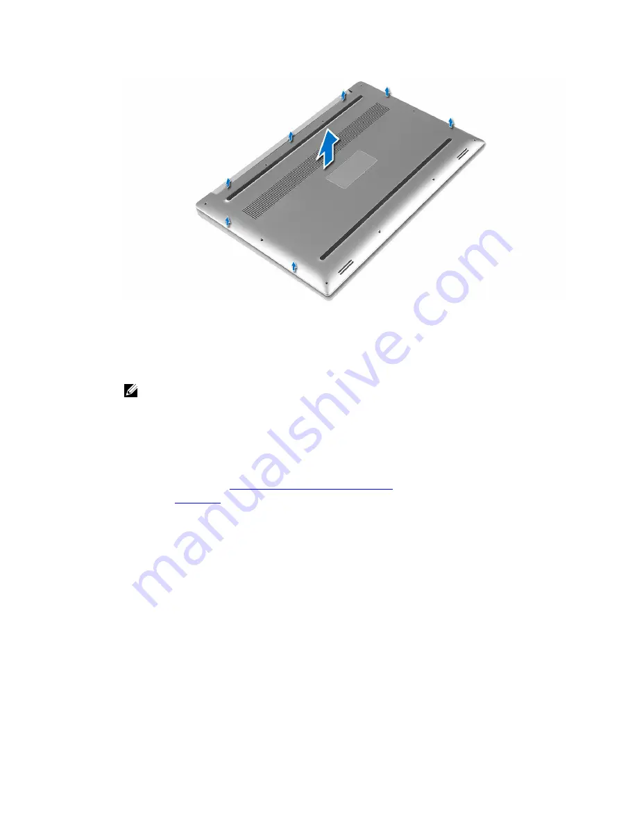
Installing the Base Cover

1.

Place the base cover on the computer and snap it in place.

2.

Tighten the screws to secure the base cover to the computer.

NOTE: Ensure you use a Torx #5 screwdriver for the base screws and a Philips screwdriver for 
the system badge screws.

3.

Turn the system badge flap over and snap it in place.

4.

Follow the procedures in 

After Working Inside Your Computer

.

Removing the Battery

1.

Follow the procedures in 

Before Working Inside Your Computer

.

2.

Remove the 

base cover

.

3.

Perform the following steps to remove the battery:
a. Disconnect the battery cable from the system board [1].
b. Remove the screws that secure the battery to the computer [2].
c. Lift the battery off the computer [3].

9

Содержание Precision 5510

Страница 1: ...Dell Precision 5510 Owner s Manual Regulatory Model P56F Regulatory Type P56F001 ...

Страница 2: ...problem WARNING A WARNING indicates a potential for property damage personal injury or death Copyright 2015 Dell Inc All rights reserved This product is protected by U S and international copyright and intellectual property laws Dell and the Dell logo are trademarks of Dell Inc in the United States and or other jurisdictions All other marks and names mentioned herein may be trademarks of their res...

Страница 3: ...d Drive 11 Installing the Hard Drive 12 Removing the Speakers 12 Installing the Speakers 13 Removing the WLAN Card 13 Installing the WLAN Card 14 Removing the Fans 14 Installing the Fans 16 Removing the Heatsink 16 Installing the Heatsink 17 Removing the DC in Connector 17 Installing the DC in Adapter Port 18 Removing the System Board 18 Installing the System Board 20 Removing the Keyboard 20 Inst...

Страница 4: ...rd 32 Assigning a system password and setup password 33 Deleting or changing an existing system and or setup password 33 4 Diagnostics 34 Enhanced Pre Boot System Assessment ePSA diagnostics 34 Device Status Light 35 5 Technical Specifications 36 6 Contacting Dell 42 4 ...

Страница 5: ...iodically touching an unpainted metal surface such as a connector on the back of the computer CAUTION Handle components and cards with care Do not touch the components or contacts on a card Hold a card by its edges or by its metal mounting bracket Hold a component such as a processor by its edges not by its pins CAUTION When you disconnect a cable pull on its connector or on its pull tab not on th...

Страница 6: ... ExpressCards or Smart Cards from the appropriate slots Turning off Your Computer CAUTION To avoid losing data save and close all open files and exit all open programs before you turn off your computer You can turn off your computer in two ways 1 Using the power button 2 Using the charms menu Using power button 1 Press and hold the Power button to turn off the screen Using charms 1 Swipe from the ...

Страница 7: ...a network cable first plug the cable into the network device and then plug it into the computer 3 Replace the battery 4 Connect your computer and all attached devices to their electrical outlets 5 Turn on your computer 7 ...

Страница 8: ...r 1 Phillips screwdriver T5 Torx screwdriver Small plastic scribe Removing the Base Cover 1 Follow the procedures in Before Working Inside Your Computer 2 Close the display and turn the computer over 3 Turn the system badge flap over 1 and then remove the screws that secure the base cover to the computer 2 NOTE Use a Torx 5 screwdriver for the base screws and a Philips screwdriver for the screws i...

Страница 9: ...em badge screws 3 Turn the system badge flap over and snap it in place 4 Follow the procedures in After Working Inside Your Computer Removing the Battery 1 Follow the procedures in Before Working Inside Your Computer 2 Remove the base cover 3 Perform the following steps to remove the battery a Disconnect the battery cable from the system board 1 b Remove the screws that secure the battery to the c...

Страница 10: ...ter Working Inside Your Computer Removing the Memory Module s 1 Follow the procedures in Before Working Inside Your Computer 2 Remove the a base cover b battery 3 Pry the securing clips away from the memory module until it pops up Remove the memory module from its connector on the system board Installing the Memory Module s 1 Insert the memory module into the memory socket 2 Press the memory modul...

Страница 11: ...Before Working Inside Your Computer 2 Remove the a base cover b battery 3 Perform the following steps to remove the hard drive bracket from the computer a Remove the screws securing the hard drive bracket to the computer 1 b Lift the hard drive bracket off the computer 2 4 Perform the following steps to remove the hard drive a Disconnect the hard drive cable from the system board 1 b Lift the hard...

Страница 12: ...he screw holes on the hard drive assembly 6 Replace the screws that secure the hard drive cage to the palm rest assembly 7 Install the a battery b base cover 8 Follow the procedures in After Working Inside Your Computer Removing the Speakers 1 Follow the procedures in Before Working Inside Your Computer 2 Remove the a base cover b battery 3 Perform the following steps to remove the speaker a Disco...

Страница 13: ...battery b base cover 6 Follow the procedures in After Working Inside Your Computer Removing the WLAN Card 1 Follow the procedures in Before Working Inside Your Computer 2 Remove the a base cover b battery 3 Perform the following steps to remove the WLAN card a Remove the screw to release the bracket that secures the WLAN card to the computer 1 and lift the bracket away from the computer 2 b Discon...

Страница 14: ...cable color scheme for the WLAN card supported by your computer is as follows Table 1 Antenna Cable Color Scheme for the WLAN Card Connectors on the WLAN card Antenna cable color Main white triangle white Auxiliary black triangle black Multiple input multiple output grey triangle Grey optional 4 Tighten the screw to secure the bracket and the WLAN card to the palmrest assembly 5 Install the a batt...

Страница 15: ...ard 3 c Remove the screws that secure the fan to the computer 4 d Lift the fan away from the computer 5 4 Perform the following steps to remove the right system fan a Un thread the LVDS cable from its restraints 1 b Disconnect the fan cable from the system board 2 c Remove the screws that secure the fan to the computer 3 d Lift the fan away from the computer 4 15 ...

Страница 16: ...able to the system board f Route the touch screen cable through the routing guides on the right fan g Adhere the tape that secures the touch screen cable to the right fan h Connect the display cable to the system board i Replace the screws that secure the right fan to the system board 2 Follow the procedures in After Working Inside Your Computer Removing the Heatsink 1 Follow the procedures in Bef...

Страница 17: ... Follow the procedures in After Working Inside Your Computer Removing the DC in Connector 1 Follow the procedures in Before Working Inside Your Computer 2 Remove the a base cover b battery 3 Perform the following steps to remove the I O board a Disconnect the DC in cable from the system board 1 b Remove the screw that secures the DC in cable to the computer c Remove the DC in connector from the co...

Страница 18: ...base cover 6 Follow the procedures in After Working Inside Your Computer Removing the System Board 1 Follow the procedures in Before Working Inside Your Computer 2 Remove the a base cover b battery c fans d heatsink e SSD f memory modules NOTE Your computer s Service Tag is located under the system badge flap You must enter the Service Tag in the BIOS after you replace the system board NOTE Before...

Страница 19: ...hen disconnect the LVDS cable from the system board 3 4 Slide out the connector latches to disconnect all the cables from the system board 5 Perform the following steps to remove the system board from the computer a Remove the screws that secure the system board to the computer 1 b Lift the system board off the computer 2 19 ...

Страница 20: ...n the screw hole on the display cable bracket with the screw hole on the system board 6 Follow the procedures in After Working Inside Your Computer Removing the Keyboard 1 Follow the procedures in Before Working Inside Your Computer 2 Remove the a base cover b battery c fans d heatsink e SSD f memory modules g system board 3 Perform the following steps to disconnect the keyboard and backlight conn...

Страница 21: ...4 Un route the LVDS cable 1 and then remove the screws that secure the keyboard to the computer 2 5 Lift and remove the keyboard from the computer 21 ...

Страница 22: ... cable and keyboard backlight cable to the keyboard controls board 6 Install the a system board b hard drive c base cover 7 Follow the procedures in After Working Inside Your Computer Removing the Display Assembly 1 Follow the procedures in Before Working Inside Your Computer 2 Remove the a base cover b battery 3 Perform the following steps a Disconnect the left LVDS cable 1 b Remove the screw sec...

Страница 23: ...4 Place the computer at the edge of a table as shown and remove the screws 1 securing the display assembly to the computer Then lift the display assembly off the computer 2 23 ...

Страница 24: ...splay hinges to the palm rest assembly 4 Adhere the tape and route the touch screen cable through the routing guides on the fan 5 Connect the touch screen cable and display cable to the system board 6 Replace the screw that secures the display cable bracket to the system board 7 Follow the procedures in After Working Inside Your Computer Removing the Solid State Drive SSD 1 Follow the procedures i...

Страница 25: ...rmal pad from the SSD NOTE The thermal pad is applicable only for a PCIe SSD card Installing the solid state drive 1 Adhere the thermal pad to the solid state drive NOTE The thermal pad is applicable only for a PCIe SSD card 2 Slide the solid state drive at an angle into the solid state drive slot 25 ...

Страница 26: ...her end of the solid state drive down and replace the screw that secures the solid state drive to the system board 4 Install the a battery b base cover 5 Follow the procedures in After Working Inside Your Computer 26 ...

Страница 27: ...on Self Test POST when the Dell logo appears you can Access System Setup by pressing F2 key Bring up the one time boot menu by pressing F12 key The one time boot menu displays the devices that you can boot from including the diagnostic option The boot menu options are Removable Drive if available STXXXX Drive NOTE XXX denotes the SATA drive number Optical Drive Diagnostics NOTE Choosing Diagnostic...

Страница 28: ...etup Options NOTE Depending on your computer and its installed devices the items listed in this section may or may not appear Table 3 Main Option Description System Time Date Allows you to set the date and time BIOS Version Displays the BIOS version Product Name Displays the product name Dell Precision M3800 Default Setting Service Tag Displays the service tag Asset Tag Displays the asset tag None...

Страница 29: ...Virtualization feature Enabled Default Setting USB Emulation Allows you to enable or disable the USB Emulation feature Enabled Default Setting USB PowerShare Allows you to enable or disable the USB PowerShare feature Enabled Default Setting USB Wake Support This option allows you to enable USB devices to wake the system from Standby Disable Default Setting SATA Operation Displays the SATA Operatio...

Страница 30: ...word NOTE Successful password changes take effect immediately System Password Allows you to set change or delete the system password NOTE Successful password changes take effect immediately HDD Password Allows you to set change or delete the administrator password Password Change Allows you to enable or disable permissions to set a System password and a Hard Drive password when the admin password ...

Страница 31: ...t feature Disabled Default Setting Windows 7 Enabled Windows 8 1 Load Legacy Option ROM This option enables or disables the Load Legacy Option ROM feature Enabled Default Setting Windows 7 Disabled Windows 8 1 Set Boot Priority Allows you to change the order in which the computer attempts to find an operating system 1 st Boot Priority CD DVD CD RW Drive 2nd Boot Priority Network 3rd Boot Priority ...

Страница 32: ... update To do this for your product click Analyze System for Updates and follow the instructions on the screen 10 Select your preferred download method in the Please select your download method below window click Download File The File Download window appears 11 Click Save to save the file on your computer 12 Click Run to install the updated BIOS settings on your computer Follow the instructions o...

Страница 33: ... 5 Select Setup Password type your system password and press Enter or Tab A message prompts you to re type the setup password 6 Type the setup password that you entered earlier and click OK 7 Press Esc and a message prompts you to save the changes 8 Press Y to save the changes The computer reboots Deleting or changing an existing system and or setup password Ensure that the Password Status is Unlo...

Страница 34: ...ons to provide extra information about the failed device s View status messages that inform you if tests are completed successfully View error messages that inform you of problems encountered during testing CAUTION Use the system diagnostics to test only your computer Using this program with other computers may cause invalid results or error messages NOTE Some tests for specific devices require us...

Страница 35: ...Device Status Light Table 8 Icon Description Turns on when you turn on the computer 35 ...

Страница 36: ... 64 and IA 32 Architecture BIOS Chip NVRAM 8 MB Table 10 Processor Feature Specification Processor type 6th Generation Intel Core i3 6th Generation Intel Quad Core i5 6th Generation Intel Quad Core i7 L1 cache up to 256 KB cache depending on processor type L2 cache up to 1024 KB cache depending on processor type L3 cache up to 6144 KB cache depending on processor type Table 11 Memory Feature Speci...

Страница 37: ... Dongle provided in box NOTE No RJ45 10 100 1000Base T IPv6 provided Wireless Wi Fi 802 11ac Wi Fi 802 11a g n Bluetooth 4 1 Intel WiDi optional Table 15 Ports and Connectors Feature Specification Audio One headset port headphone and microphone combo USB 3 0 two USB 3 0 ports with PowerShare One Thunderbolt 3 port with PowerShare USB C Video one HDMI 1 4 Memory card reader SD 4 0 Table 16 Display ...

Страница 38: ...60 Hz Minimum viewing angles Horizontal 80 80 Vertical 80 80 Table 17 Keyboard Feature Specification Number of keys United States 80 keys United Kingdom 81 keys Brazil 81 keys Japan 84 keys Layout QWERTY AZERTY Kanji Table 18 Touchpad Feature Specification Active Area X axis 105 mm Y axis 80 mm Table 19 Camera Feature Specification Type HD Camera Digital Array Microphone Still Resolution 0 92 mega...

Страница 39: ...ecification Type Li polymer 3 cell 56 Whr 6 cell 84 Whr Dimensions 56 Whr Depth 223 20 mm 8 79 in Height 7 20 mm 0 28 in Width 71 80 mm 2 83 in Weight 0 54 lb 0 24 kg 84 Whr Depth 330 50 mm 13 01 in Height 7 20 mm 0 28 in Width 71 80 mm 2 83 in Weight 0 76 lb 0 34 kg Voltage 11 4 V Life span 300 discharge charge cycles Temperature range Operating approximate Charge 0 C to 50 C 32 F to 158 F Discha...

Страница 40: ...o 40 C 32 F to 104 F Non Operating 40 C to 70 C 40 F to 158 F Table 23 Physical Dimensions Physical Specification Height 17 mm 0 66 in Width 357 mm 14 06 in Depth 235 mm 9 27 in Weight Minimum 2 kg 4 41 lb Table 24 Environmental Feature Specification Temperature range Operating 0 C to 40 C 32 F to 104 F Storage 40 C to 70 C 40 F to 158 F Relative humidity maximum Operating 10 to 90 non condensing ...

Страница 41: ...fication Operating 110 G 2 ms Non operating 160 G 2 ms Altitude Operating 15 2 m to 3048 m 50 to 10 000 ft Storage 15 2 m to 10 668 m 50 ft to 35 000 ft Airborne contaminant level G1 as defined by ISA S71 04 1985 41 ...

Страница 42: ...upport and service options Availability varies by country and product and some services may not be available in your area To contact Dell for sales technical support or customer service issues 1 Go to Dell com support 2 Select your support category 3 Verify your country or region in the Choose a Country Region drop down list at the bottom of the page 4 Select the appropriate service or support lin...

Отзывы: