background image

Install the:

a

Top cover

Follow the procedure in 

After working inside your computer

.

Front Input Output panel

Removing the front Input Output panel

Follow the procedure in 

Before working inside your computer

.

Remove the:

a

Top cover

NOTE: 

Take a picture or document the routing of the three cables attached to the front I/O Panel.

To remove the Intel front I/O panel:

a Press the release tabs located on the sides of the front panel cable connector and lift the cable away [1].
b Press down the metal release tab on the front panel HSD cable and slide it out of the socket [2].
c Disconnect the front panel power connector cable [3].

Removing and installing components

51

Содержание Precision 3930 Rack

Страница 1: ...Dell Precision 3930 Rack Service Manual Regulatory Model D02R Regulatory Type D02R001 ...

Страница 2: ...amage to hardware or loss of data and tells you how to avoid the problem WARNING A WARNING indicates a potential for property damage personal injury or death 2018 Dell Inc or its subsidiaries All rights reserved Dell EMC and other trademarks are trademarks of Dell Inc or its subsidiaries Other trademarks may be trademarks of their respective owners 2018 07 Rev A00 ...

Страница 3: ...bility 10 DDR4 11 DDR4 Details 11 Memory Errors 12 Processor 12 3 Removing and installing components 14 Recommended tools 14 Screw size list 14 System board layout 15 Disassembly and reassembly 15 System cover 15 Ear assembly 17 Air duct 21 Coin cell battery 24 Hard drive assembly 25 Hard drive backplane 30 Memory module 37 Heat sink 39 Processor 40 Intrusion switch 42 System fan 43 System fan cag...

Страница 4: ...ing 75 Enhanced Pre Boot System Assessment ePSA diagnostics 75 Running the ePSA Diagnostics 75 Diagnostics 75 PSU LED indicator 77 Diagnostic error messages 77 System error messages 80 5 Getting help 82 Contacting Dell 82 4 Contents ...

Страница 5: ... processor by its edges not by its pins CAUTION When you disconnect a cable pull on its connector or on its pull tab not on the cable itself Some cables have connectors with locking tabs if you are disconnecting this type of cable press in on the locking tabs before you disconnect the cable As you pull connectors apart keep them evenly aligned to avoid bending any connector pins Also before you co...

Страница 6: ...cially sensitive components such as expansion cards processors memory DIMMs and system boards Very slight charges can damage circuits in ways that may not be obvious such as intermittent problems or a shortened product life span As the industry pushes for lower power requirements and increased density ESD protection is an increasing concern Due to the increased density of semiconductors used in re...

Страница 7: ...ional office to find out if they have one To perform the test plug the wrist strap s bonding wire into the tester while it is strapped to your wrist and push the button to test A green LED is lit if the test is successful a red LED is lit and an alarm sounds if the test fails Insulator Elements It is critical to keep ESD sensitive devices such as plastic heat sink casings away from internal parts ...

Страница 8: ...ack 4 Keep the load close The closer it is to your spine the less force it exerts on your back 5 Keep your back upright whether lifting or setting down the load Do not add the weight of your body to the load Avoid twisting your body and back 6 Follow the same techniques in reverse to set the load down After working inside your computer After you complete any replacement procedure ensure that you c...

Страница 9: ...ands with a theoretically 10 times faster than its predecessor In a nutshell USB 3 1 Gen 1 features are as follows Higher transfer rates up to 5 Gbps Increased maximum bus power and increased device current draw to better accommodate power hungry devices New power management features Full duplex data transfers and support for new transfer types Backward USB 2 0 compatibility New connectors and cab...

Страница 10: ... Gen 1 opens up the laneways and provides more headroom for devices to deliver a better overall experience Where USB video was barely tolerable previously both from a maximum resolution latency and video compression perspective it s easy to imagine that with 5 10 times the bandwidth available USB video solutions should work that much better Single link DVI requires almost 2Gbps throughput Where 48...

Страница 11: ...e wrong type of memory into the system DDR4 needs 20 percent less or just 1 2 volts compared to DDR3 which requires 1 5 volts of electrical power to operate DDR4 also supports a new deep power down mode that allows the host device to go into standby without needing to refresh its memory Deep power down mode is expected to reduce standby power consumption by 40 to 50 percent DDR4 Details There are ...

Страница 12: ...630 Intel Xeon E Processor E 2176G 6 Core HT 3 7 Ghz 4 7 GHz Turbo 8 MB Integrated Intel UHD P630 Intel Xeon E Processor E 2174G 4 Core HT 3 8 Ghz 4 7 GHz Turbo 8 MB Integrated Intel UHD P630 Intel Xeon E Processor E 2146G 6 Core HT 3 5 GHz 4 5 Ghz Turbo 8 MB Integrated Intel UHD P630 Intel Xeon E Processor E 2136 6 Core HT 3 3 Ghz 4 5 Ghz Turbo 8 MB Not Supported Intel Xeon E Processor E 2134 4 C...

Страница 13: ...Core i5 8600K Processor 6 Core 9 MB Cache 3 6 GHz up to 4 3 GHz Turbo Integrated Intel UHD 630 Intel Core i7 8700 Processor 6 Core 12 MB Cache 3 2 GHz up to 4 6 GHz Turbo Integrated Intel UHD 630 Intel Core i7 8700K Processor 6 Core 12 MB Cache 3 7 GHz up to 4 7 GHz Turbo Integrated Intel UHD 630 Technology and components 13 ...

Страница 14: ...hillips 1 screwdriver Philips 2 screwdriver 5 5mm Socket wrench Plastic scribe Screw size list Table 3 Screw size list Component 6 32x6 M3x4 M2x3 5 6 32x5 System board 9 Riser 1 4 Riser 2 2 Front IO board 3 M 2 PCIe SSD card slot 2 L Ear BKT 3 R Ear BKT 3 PDB 3 CPU Fan Cage 2 3 14 Removing and installing components ...

Страница 15: ...or 13 M 2 PCIe connector SSD0 14 PCIe slot 15 M 2 PCIe connector SSD1 16 SATA 3 connector 17 PCIe slot 18 SATA 2 connector 19 Right SATA power connector 2 20 Fan 7 power connector 21 Fan 8 power connector 22 Fan 9 power connector 23 GPU power connector 24 Front panel power connector 25 Fan 6 power connector 26 Processor 27 Fan 5 4 3 power connector Disassembly and reassembly System cover Removing ...

Страница 16: ...elease the lock 1 b Pull the latch to release the top cover 2 c Lift the top cover away 3 Installing the system cover 1 Lift up the release latch and align the top cover tabs with the slots on the system chassis 1 and slide it into the slot NOTE Ensure that all internal cables are routed correctly and connected before securing the top cover 2 The release latch automatically locks the top cover to ...

Страница 17: ...edure in After working inside your computer Ear assembly Removing the left ear assembly 1 Follow the procedure in Before working inside your computer 2 To remove the left ear assembly a Remove three M3x4 that secure the left ear assembly 1 b Slide out the left ear assembly 2 Removing and installing components 17 ...

Страница 18: ...g left ear assembly 1 To install the left ear assembly a Slide the ear module into the slot 1 b Fasten the three M3x4 screws to secure the ear module to the system chassis 2 18 Removing and installing components ...

Страница 19: ... Removing the right ear assembly 1 Follow the procedure in Before working inside your computer 2 To remove the right ear assembly a Remove three M3x4 that secure the right ear assembly 1 b Slide out the right ear assembly 2 Removing and installing components 19 ...

Страница 20: ... right ear assembly 1 To install the right ear assembly a Slide the ear module into the slot 1 b Fasten the three M3x4 screws to secure the ear module to the system chassis 2 20 Removing and installing components ...

Страница 21: ...king inside your computer Air duct Removing the air duct 1 Follow the procedure in Before working inside your computer 2 Remove the top cover 3 To remove the air duct a Unroute the front panel cable Removing and installing components 21 ...

Страница 22: ...4 Lift the air duct away from the heat sink Installing the air duct 1 Align the air duct over the heat sink holding the blue point and seat it in the slot 22 Removing and installing components ...

Страница 23: ... on both sides during installation Damage to the cables could occur 2 Route the front panel cable through the cable routing on the air duct 3 Install the Top cover 4 Follow the procedure in After working inside your computer Removing and installing components 23 ...

Страница 24: ...To remove the coin cell battery a Using a plastic scribe press the release latch 1 b Remove the coin cell battery from the system 2 Installing the coin cell battery 1 Place the coin cell battery in its slot on the system board 1 2 Press the battery into the connector until it locks into place 2 24 Removing and installing components ...

Страница 25: ...failure can occur NOTE The hard drive assembly is applicable for both 2 5 inch and 3 5 inch hard drives Only one type of hard drive can be installed in a system The 2 5 inch and 3 5 inch hard drives are not interchangeable 1 Follow the procedure in Before working inside your computer 2 To remove the hard drive blank if replacing with a new hard drive a Press the release tabs on the sides of the bl...

Страница 26: ...e release latch 2 b Pull the hard drive assembly away from the system 3 4 To remove the hard drive from the assembly bracket a Using Philips screwdriver remove the screws from the slide rails on the hard drive bracket 1 b Lift the hard drive out of the hard drive bracket 2 26 Removing and installing components ...

Страница 27: ...d drive assembly 1 To install the hard drive in the assembly bracket a Align the hard drive within the drive bracket 1 b Secure the hard drive to the drive bracket with the screws 2 Removing and installing components 27 ...

Страница 28: ...stall the hard drive a Insert the hard drive assembly into the hard drive slot 1 b Push the release latch back into closed position to secure the hard drive in the slot 2 28 Removing and installing components ...

Страница 29: ...ot occupied by a hard drive a Insert the hard drive blank into the hard drive slot and slide it in 4 Follow the procedure in After working inside your computer NOTE All hard drive slots should be populated with either a hard drive assembly or hard drive blank to ensure proper system cooling and air flow Removing and installing components 29 ...

Страница 30: ... To remove the left hard drive backplane a Disconnect the SATA 0 connector cable and the SATA 1 connector cable for 2 5 inch hard drive back plane 1 Disconnect the SATA power cable 2 b Un route the cables from the cable retention clips provided 3 a Loosen the one captive screw 1 lift the HDD backplane away from the system chassis 2 30 Removing and installing components ...

Страница 31: ...rive backplane 1 Align and place the hard drive backplane on the alignment pins provided on the hard drive cage 1 2 Fasten the captive screw to secure the backplane to the hard drive cage 2 Removing and installing components 31 ...

Страница 32: ...the hard drive cage 3 Re route the SATA power cable and the SATA connector cables through the cable retention clip 1 4 Connect the SATA power cable 2 the SATA 0 connector cable 3 and SATA 1 connector cable for 2 5 inch hard drive back plane 32 Removing and installing components ...

Страница 33: ...nside your computer Removing right hard drive backplane 1 Follow the procedure in Before working inside your computer 2 Remove the a Top cover b Air duct c Hard drives 3 To remove the right hard drive backplane a Disconnect the SATA 2 connector cable and the SATA 3 connector cable for 2 5 inch hard drive back plane 1 Disconnect the SATA power cable 2 b Un route the cables from the cable retention ...

Страница 34: ...a Loosen the one captive screw 1 lift the HDD backplane away from the system chassis 2 34 Removing and installing components ...

Страница 35: ...drive backplane 1 Align and place the hard drive backplane on the alignment pins provided on the hard drive cage 1 2 Fasten the captive screw to secure the backplane to the hard drive cage 2 Removing and installing components 35 ...

Страница 36: ...s through the cable retention clip 1 4 Connect the SATA power cable 2 the SATA 2 connector cable 3 and SATA 3 connector cable for 2 5 inch hard drive back plane NOTE The blue SATA signal cable plugs into the blue connector on the system board The black SATA signal cable plugs into the black connector on the system board 36 Removing and installing components ...

Страница 37: ...he memory modules to cool after you power off the system Handle the memory module by the card edges and avoid touching the components or metallic contacts on the memory module 2 Remove the a Top cover b Air duct 3 To remove the memory module a Press open the retention tabs from both sides to lift the memory module from the connector 1 b Remove the memory module from the system board 2 Removing and...

Страница 38: ...er of the memory module apply pressure at both ends of the memory module evenly NOTE The memory module connector has an alignment key that enables you to install the memory module in the connector in only one orientation 3 Press the memory module with your thumbs until the retention tabs firmly click into place 2 4 Repeat step 1 through step 4 of this procedure to install the remaining memory modu...

Страница 39: ...eat sink and lift it away from the system NOTE Ensure that the screw is completely loosened before moving on to the next screw NOTE Loosen the screws in a sequential order 1 2 3 4 as shown on the heat sink label Installing heat sink 1 To install the heat sink NOTE If using an existing heat sink remove the thermal grease from the heat sink by using a clean lint free cloth CAUTION Insure the airflow...

Страница 40: ...e moving on to the next screw 2 Install the a Air duct b Top cover 3 Follow the procedure in After working inside your computer Processor Removing processor 1 Follow the procedure in Before working inside your computer 2 Remove the a Top cover b Air duct c Heat sink 3 To remove the processor a Release the socket lever by pushing the lever down and out from under the tab on the processor shield 1 b...

Страница 41: ...w 2 3 Lower the socket lever and push it under the tab to lock it 3 4 Use the thermal grease syringe included with the processor kit Apply the grease in a spiral design on top of the processor 4 CAUTION Applying too much thermal grease can result in excessive grease coming in contact with and contaminating the processor socket NOTE The thermal grease is intended for one time use only Dispose of th...

Страница 42: ...witch cable from the connector on the system board 1 b Pull the intrusion switch release tab and lift it away from the system 2 Installing the intrusion switch NOTE Insure the intrusion switch is completely seated and latched in place 1 Insert the intrusion switch into the slot on the chassis 1 2 Connect the intrusion switch cable to the system board 2 42 Removing and installing components ...

Страница 43: ...fan 1 Follow the procedure in Before working inside your computer 2 Remove the a Top cover b Air duct if required 3 To remove the system fan a Disconnect the system fan cable from the system board b Lift the blue release pins on the system fan c Lift the fan away from the fan cage Removing and installing components 43 ...

Страница 44: ...ase pins of the fan and the slot of the fan cage b Push down the blue release pins until it sits in the slot c Connect the system fan cable to the system board NOTE Fold and tuck excess fan cable in the gap on the left side of the fan 44 Removing and installing components ...

Страница 45: ...ollow the procedure in Before working inside your computer 2 Remove the a Top cover b Air duct c System fan 3 To remove the system fan cage a Remove the two 6 32x5 that secures the fan cage to the chassis 1 b Slide the fan cage to the right until the retention clips disengage 2 c Lift the fan cage away from the chassis Removing and installing components 45 ...

Страница 46: ...age a Lower the fan cage into the chassis aligning the retention clips into the guide slots b Slide the fan cage to the left until the retention clips engage 1 c Fasten the two 6 32x5 to secure the fan cage to the chassis 2 46 Removing and installing components ...

Страница 47: ...working inside your computer 2 Remove the a Top cover b Air duct c System fan 3 To remove the graphics card fan cage a Un route the SATA power cable and the SATA connector cables from the retention clip on the side of the graphics card fan cage 1 b Loosen the two 6 32x5 that secures the fan cage to the chassis 2 and the lift the cage away from the system chassis 3 Removing and installing component...

Страница 48: ...into the chassis aligning the retention clips into the guide slots 1 b Fasten the two 6 32x5 to secure the fan cage to the chassis 2 c Re route the SATA power cable and the SATA connector cables through the cable retention clip on the graphics card fan cage 3 48 Removing and installing components ...

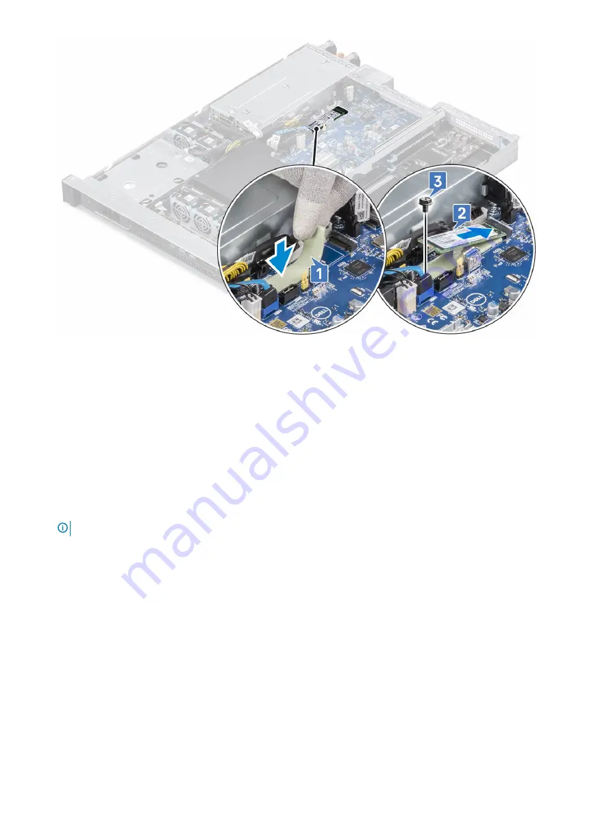
Страница 49: ...e M 2 PCIe Solid State Drive SSD 1 Follow the procedure in Before working inside your computer 2 Remove the a Top cover 3 To remove the M 2 PCIe SSD card a Remove the single M2x3 5 screw that secures the M 2 PCIe SSD card to the system board 1 b Lift and pull out the SSD card from its connector on the system board 2 Removing and installing components 49 ...

Страница 50: ...e SSD 1 Place the thermal pad into the slot on the system board 1 2 Insert the M 2 PCIe SSD card into the card slot on the system board 2 3 Replace the single M2x3 5 screw that secures the M 2 PCIe SSD card to the system board 3 50 Removing and installing components ...

Страница 51: ...over NOTE Take a picture or document the routing of the three cables attached to the front I O Panel 3 To remove the Intel front I O panel a Press the release tabs located on the sides of the front panel cable connector and lift the cable away 1 b Press down the metal release tab on the front panel HSD cable and slide it out of the socket 2 c Disconnect the front panel power connector cable 3 Remo...

Страница 52: ...4 Remove the three 6 32x5 screws that secure the I O panel to the system chassis 1 lift the I O panel away from the system chassis 2 52 Removing and installing components ...

Страница 53: ...not properly installed 1 Align the front I O panel with the slots on the system chassis 1 2 Replace the three 6 32x5 screw that secures the front I O panel to the system chassis 2 3 Reconnect the Front panel cable 1 front panel HSD cable 2 and the front panel power cable 3 NOTE Refer to cable routing picture or document and insure the three cables are properly routed from the I O panel to the syst...

Страница 54: ...ur computer Power supply unit PSU Removing power supply unit 1 Follow the procedure in Before working inside your computer 2 To remove the PSU a Press the release latch on the PSU 1 b Pull the PSU out of the slot and away from the system 2 54 Removing and installing components ...

Страница 55: ...Installing the power supply unit 1 Insert the PSU in the chassis and slide it into the slot until it locks Removing and installing components 55 ...

Страница 56: ... a Second PSU blank b Top cover c Second PSU fan blank 3 Install the a Second PSU fan b Connect fan cable to power distribution board FAN2 connector NOTE Refer to the System fan section NOTE Fold and tuck excess fan cable in the gap on the left side of the fan c Insert the PSU in the chassis and slide it into the slot until it locks 56 Removing and installing components ...

Страница 57: ...r distribution board a Press the release tabs located on the sides of the power distribution board connector and lift the cable away 1 b Disconnect the two power supply unit fan connectors 2 c Press the release tabs of the power distribution board power supply connector and disconnect the cable 3 d Remove the three 6 32x6 screws that secure the power distribution board 4 e Lift away the power dist...

Страница 58: ...on the system chassis 1 2 Replace the three 6 32x6 screw that secures the power distribution board to the system board 2 3 Reconnect the power distribution board power cable 3 power supply unit fan cables 4 and the power distribution board connector 5 58 Removing and installing components ...

Страница 59: ...our computer Expansion card Riser 1 module Removing riser1 module 1 Follow the procedure in Before working inside your computer 2 Remove the a Top cover 3 To remove the riser1 module a Holding the two blue lift points and pull the riser1 module from the slot Removing and installing components 59 ...

Страница 60: ... blue contact points align the module with the alignment pins on the chassis and insert the riser1 module into the slot 2 Install the a Top cover 3 Follow the procedure in After working inside your computer 60 Removing and installing components ...

Страница 61: ...om the slot Installing the riser1 blank NOTE A riser1 blank must be installed over an empty expansion card slot to maintain Federal Communications Commission FCC certification of the system The blank also keep dust and dirt out of the system and aid in proper cooling and airflow inside the system 1 Insert the riser1 blank into the slot and close the release tab to secure the riser1 blank in place ...

Страница 62: ... Before working inside your computer 2 Remove the a Top cover b Riser 1 module 3 To remove the riser1 graphics card NOTE If installed disconnect graphics card power cable from graphics card a Pull the release tab 1 to open the riser1 slot b Push the release tab on the PCIe slot 2 lift out the graphics card from the slot 3 62 Removing and installing components ...

Страница 63: ...Insert the riser1 graphics card into the slot 1 and close the release tab to secure the riser1 graphics card in place 2 NOTE Ensure that the graphics card bracket is installed correctly in the slot 2 Install the a Riser 1 module b Top cover 3 Follow the procedure in After working inside your computer Removing and installing components 63 ...

Страница 64: ...ab on the PCIe slot 3 lift out the graphics card from the slot 4 NOTE If removing the dual graphics card permanently install two Riser1 blanks in empty expansion slot opening Installing the Riser1 Dual Graphics Card 1 Reconnect the graphics card power cable 1 insert the dual graphics card into the PCIe slot 2 2 Close the release tab to secure the riser1 dual graphics card in place 3 NOTE Ensure th...

Страница 65: ... card 1 Follow the procedure in Before working inside your computer 2 Remove the a Top cover b Riser 1 module 3 Removing the riser 1 dell ultra speed drive duo card a Pull the release tab 1 and open the riser 1 slot b Push the release tab on the PCIe slot 2 lift out the Dell Ultra speed Drive Duo Card from slot 3 Removing and installing components 65 ...

Страница 66: ...e Dell Ultra speed Drive Duo Card cover 1 remove the one M3x3 5 screw 2 and take out the SSD card 3 NOTE If removing the Dell Ultra speed Drive Duo Card permanently install Riser1 blank in empty expansion slot 2 opening 66 Removing and installing components ...

Страница 67: ...open 2 Remove the one M2x2 5 screw 3 2 To install the M 2 SSD a Insert the SSD card into the slot on the module 1 Replace the one M2x2 5 screw 2 that secures the SSD card and close the module cover 3 3 Slide the Dell Ultra speed Drive Duo Card into the riser 1 slot 2 1 Close the riser 1 module release latch 2 Removing and installing components 67 ...

Страница 68: ... procedure in After working inside your computer Removing riser 2 module 1 Follow the procedure in Before working inside your computer 2 Remove the a Top cover 3 To remove the riser 2 module a Locate the blue points on the riser 2 module Grab the blue points and lift the riser 2 module away from the system chassis 68 Removing and installing components ...

Страница 69: ...he PCIe slot 3 Install the a Top cover 4 Follow the procedure in After working inside your computer Removing riser 2 blank 1 Follow the procedure in Before working inside your computer 2 Remove the a Top cover b Riser 2 module 3 To remove the riser 2 blank a Pull the release tab 1 to open the riser2 slot and lift out the riser2 blank from the slot 2 Removing and installing components 69 ...

Страница 70: ...d aid in proper cooling and airflow inside the system 2 Install the a Riser 2 module b Top cover 3 Follow the procedure in After working inside your computer System board Removing system board 1 Follow the procedure in Before working inside your computer 2 Remove the a Top cover b Air duct c System Fan d System fan cage e Memory module f Heat sink g Processor h M 2 PCIe Solid State Drive if instal...

Страница 71: ...p on the system board c Disconnect the SATA 2 power cable and the SATA 2 SATA 3 if installed cable 5 and lift to gain access to disconnect the GPU fan cables 4 To remove the system board screws and system board 5 Remove the nine 6 32 screws that secure the system board 1 lift the front of the system board gently pull it toward the front of the chassis to disengage the connectors from the rear wall...

Страница 72: ...system chassis until the connectors at the back of the system board align with the slots on the chassis rear wall Move the board toward the rear wall until the screw holes on the system board align with the standoffs on the system chassis 1 3 Secure the system board to the chassis with the nine 6 32 screws 72 Removing and installing components ...

Страница 73: ...5 Reconnect the front panel power cable GPU power cable 4 6 Reconnect the SATA 2 power cable and the SATA 2 SATA 3 if disconnected cable and the GPU fan cables 5 NOTE Route all cables through the retention clips provided on the system chassis and ensure no cables are stuck under the system board during installation NOTE Refer to cable routing picture or document and insure the cables are properly ...

Страница 74: ...ntrusion switch d M 2 PCIe Solid State Drive SSD if removed e Processor f Heat sink g Memory module h System fan cage i System fan j Air duct k Top cover 8 Follow the procedure in After working inside your computer 74 Removing and installing components ...

Страница 75: ...hen the diagnostic tests are performed Running the ePSA Diagnostics 1 Invoke diagnostics boot by either of the methods suggested above 2 Once on one time boot menu use up down arrow key to navigate to ePSA or diagnostics and press return key to launch Fn PWR will flash diagnostics boot selected on screen and launch ePSA diagnostics directly 3 On the boot menu screen select the Diagnostics option 4...

Страница 76: ...2 Motherboard BIOS ROM failure Motherboard covers BIOS corruption or ROM error Power off system and install RTC_RST jumper Remove jumper and power back on to see if issue persist Make sure system stays ON and 2 2 code repeats when this happen or it might just be a false alarm If truly is the 2 2 blink code replace MB 2 3 Memory No Memory RAM detected Make sure a supported DIMM is installed Try dif...

Страница 77: ... Flashing Green When hot adding a power supply this indicates that the power supply is mismatched with the other power supply in terms of efficiency features set health status and supported voltage Diagnostic error messages Table 6 Diagnostic error messages Error messages Description AUXILIARY DEVICE FAILURE The touchpad or external mouse may be faulty For an external mouse check the cable connect...

Страница 78: ...ostics HARD DISK DRIVE CONTROLLER FAILURE 0 The hard drive does not respond to commands from the computer Shut down the computer remove the hard drive and boot the computer from an optical drive Then shut down the computer reinstall the hard drive and restart the computer If the problem persists try another drive Run the Hard Disk Drive tests in Dell Diagnostics HARD DISK DRIVE FAILURE The hard dr...

Страница 79: ...ALUE A memory module may be faulty or improperly seated Reinstall the memory module or if necessary replace it MEMORY WRITE READ FAILURE AT ADDRESS READ VALUE EXPECTING VALUE A memory module may be faulty or improperly seated Reinstall the memory module or if necessary replace it NO BOOT DEVICE AVAILABLE The computer cannot find the hard drive If the hard drive is your boot device ensure that the ...

Страница 80: ...error messages Table 7 System error messages System message Description Alert Previous attempts at booting this system have failed at checkpoint nnnn For help in resolving this problem please note this checkpoint and contact Dell Technical Support The computer failed to complete the boot routine three consecutive times for the same error CMOS checksum error RTC is reset BIOS Setup default has been...

Страница 81: ...System message Description out of range may or may not indicate a potential hard drive problem Troubleshooting 81 ...

Страница 82: ...port and service options Availability varies by country and product and some services may not be available in your area To contact Dell for sales technical support or customer service issues 1 Go to Dell com support 2 Select your support category 3 Verify your country or region in the Choose a Country Region drop down list at the bottom of the page 4 Select the appropriate service or support link ...

Отзывы: