background image

Speakers

Removing the speakers

Prerequisites

1. Follow the procedure in 

before working inside your computer

.

2. Remove the 

SD Card

.

3. Remove the 

base cover

.

4. Disconnect the 

battery

.

About this task

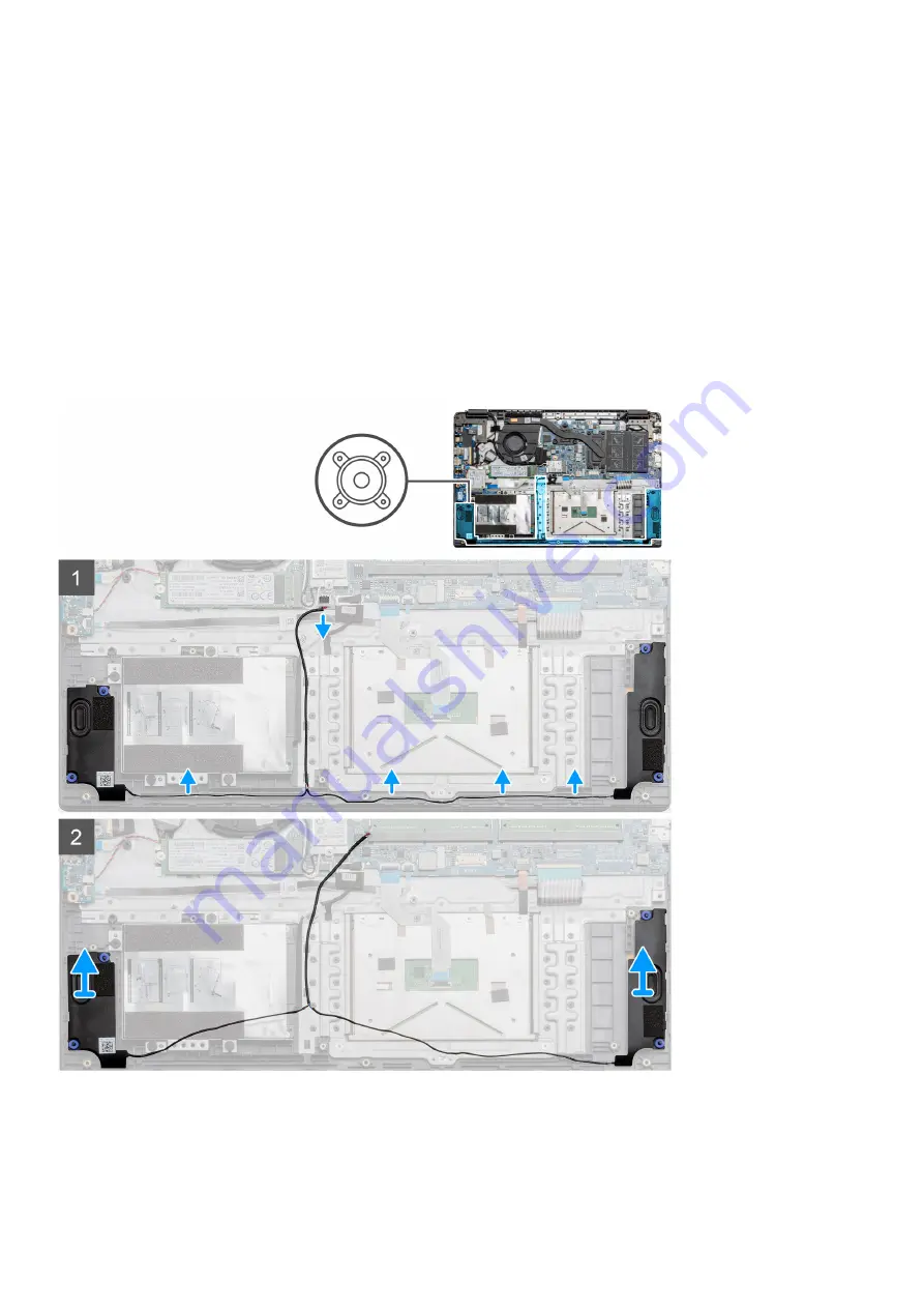
The figure indicates the location of the speakers and provides a visual representation of the removal procedure.

Steps

1. Disconnect the Speaker cable from the connector on the system board and lift the connected cables from the routing points on the

lower portion of the palmrest.

2. Ensure the cables are free and lift the speaker modules from both ends of the computer.

46

Disassembly and reassembly

Содержание Precision 3510

Страница 1: ...Latitude 3510 Service Manual 1 Regulatory Model P101F Regulatory Type P101F001 P101F001 May 2020 Rev A00 ...

Страница 2: ...ential damage to hardware or loss of data and tells you how to avoid the problem WARNING A WARNING indicates a potential for property damage personal injury or death 2020 Dell Inc or its subsidiaries All rights reserved Dell EMC and other trademarks are trademarks of Dell Inc or its subsidiaries Other trademarks may be trademarks of their respective owners ...

Страница 3: ...ential damage to hardware or loss of data and tells you how to avoid the problem WARNING A WARNING indicates a potential for property damage personal injury or death 2020 Dell Inc or its subsidiaries All rights reserved Dell EMC and other trademarks are trademarks of Dell Inc or its subsidiaries Other trademarks may be trademarks of their respective owners ...

Страница 4: ... 18 Installing the microSD card 19 SIM card 19 Removing the SIM card 19 Installing the SIM card 21 Base cover 21 Removing the base cover 21 Installing the base cover 23 Battery 25 Lithium ion battery precautions 25 Removing the battery 25 Installing the battery 26 Memory modules 27 Removing the memory module 27 Installing the memory modules 28 WLAN card 30 Removing the WLAN card 30 Installing the ...

Страница 5: ...y UMA 51 Installing the Heatsink Assembly UMA 52 System board 53 Removing the system board Discrete 53 Installing the system board Discrete 56 Removing the system board UMA 58 Installing the system board UMA 60 IO Board 63 Removing the IO Board 63 Installing the IO Board 64 Power button 65 Removing the Power Button 65 Installing the Power Button 66 Display assembly 67 Removing the LCD Assembly 67 ...

Страница 6: ... a wrist grounding strap or by periodically touching an unpainted metal surface at the same time as touching a connector on the back of the computer CAUTION Handle components and cards with care Do not touch the components or contacts on a card Hold a card by its edges or by its metal mounting bracket Hold a component such as a processor by its edges not by its pins CAUTION When you disconnect a c...

Страница 7: ... cards processors memory DIMMs and system boards Very slight charges can damage circuits in ways that may not be obvious such as intermittent problems or a shortened product life span As the industry pushes for lower power requirements and increased density ESD protection is an increasing concern Due to the increased density of semiconductors used in recent Dell products the sensitivity to static ...

Страница 8: ...ive devices such as plastic heat sink casings away from internal parts that are insulators and often highly charged Working Environment Before deploying the ESD Field Service kit assess the situation at the customer location For example deploying the kit for a server environment is different than for a desktop or portable environment Servers are typically installed in a rack within a data center d...

Страница 9: ...e network device and then plug it into the computer 2 Connect your computer and all attached devices to their electrical outlets 3 Turn on your computer 4 If required verify that the computer works correctly by running the diagnostic tool Working on your computer 9 ...

Страница 10: ...y 10 times faster than its predecessor In a nutshell USB 3 2 Gen 1 features are as follows Higher transfer rates up to 5 Gbps Increased maximum bus power and increased device current draw to better accommodate power hungry devices New power management features Full duplex data transfers and support for new transfer types Backward USB 2 0 compatibility New connectors and cable The topics below cove...

Страница 11: ...dwidth available USB video solutions should work that much better Single link DVI requires almost 2Gbps throughput Where 480Mbps was limiting 5Gbps is more than promising With its promised 4 8Gbps speed the standard will find its way into some products that previously weren t USB territory like external RAID storage systems Listed below are some of the available Super Speed USB 3 2 Gen 1 products ...

Страница 12: ... the device and the cable have to support USB Power Delivery Just having a USB Type C connection doesn t necessarily mean they do USB Type C and USB 3 1 USB 3 1 is a new USB standard USB 3 s theoretical bandwidth is 5 Gbps while USB 3 1 s is 10 Gbps That s double the bandwidth as fast as a first generation Thunderbolt connector USB Type C isn t the same thing as USB 3 1 USB Type C is just a connec...

Страница 13: ...lows an HDMI connected TV with a built in tuner to send audio data upstream to a surround audio system eliminating the need for a separate audio cable 3D Defines input output protocols for major 3D video formats paving the way for true 3D gaming and 3D home theater applications Content Type Real time signaling of content types between display and source devices enabling a TV to optimize picture se...

Страница 14: ...tandby S3 SOix LED is off System is Off Hibernating S4 S5 LED is off Power On and LED behavior with Fingerprint reader Pressing the power button for a duration between 50 msec to 2 sec turns on the device Power button does not register additional presses until the SOL Sign Of Life has been provided to the user System LED s illuminates upon pressing the power button All the available LED s Keyboard...

Страница 15: ...harging When the charge is complete the LED turns off If the computer is running on a battery the battery light operates as follows 1 Off the battery is adequately charged or the computer is turned off 2 Solid amber the battery charge is critically low A low battery state is approximately 30 minutes or less of battery life remaining Camera LED White LED activates when camera is on Mic Mute LED Whe...

Страница 16: ...rt 4 Heatsink 5 Memory Modules 6 Speakers 7 System Board 8 Touchpad 9 Palmrest Assembly 10 Display Assembly 11 Power Button Module 12 Daughterboard Module 13 Coin cell Battery 14 IO Board 15 WLAN Card 16 Fan Assembly 17 WWAN Card 3 16 Major components of your system ...

Страница 17: ...ist of components and their part numbers for the original system configuration purchased These parts are available according to warranty coverages purchased by the customer Contact your Dell sales representative for purchase options Major components of your system 17 ...

Страница 18: ...g the microSD card Prerequisites 1 Follow the procedure in Before working inside your computer About this task Steps 1 Push the microSD card to release it from the computer 2 Slide the microSD card out of the computer 4 18 Disassembly and reassembly ...

Страница 19: ...on the computer 2 Slide the microSD card into the slot until it clicks into place Next steps Follow the procedures in After working inside your computer SIM card Removing the SIM card Prerequisites 1 Follow the procedure in Before working inside your computer Disassembly and reassembly 19 ...

Страница 20: ...at covers the SIM card slot to release it from the system 2 Insert a SIM card remover tool in the slot and push it to eject the SIM card tray 3 Pull the SIM card try and remove the SIM card from the SIM card tray 20 Disassembly and reassembly ...

Страница 21: ...card tray 2 3 Pull the SIM card holder out of the slot 4 Place the SIM card into the SIM card holder 5 Slide the SIM card tray into the slot until it clicks into place Next steps Follow the procedures in After working inside your computer Base cover Removing the base cover Prerequisites 1 Follow the procedure in before working inside your computer 2 Remove the SD Card Disassembly and reassembly 21...

Страница 22: ...About this task 22 Disassembly and reassembly ...

Страница 23: ...ing a plastic scribe pry the base cover from the top right corner and lift the base cover away from the computer Installing the base cover Prerequisites If you are replacing a component remove the existing component before performing the installation procedure Disassembly and reassembly 23 ...

Страница 24: ...About this task The figure indicates the location of the base cover and provides a visual representation of the installation procedure 24 Disassembly and reassembly ...

Страница 25: ...atures or disassemble battery packs and cells Do not apply pressure to the surface of the battery Do not bend the battery Do not use tools of any kind to pry on or against the battery Ensure any screws during the servicing of this product are not lost or misplaced to prevent accidental puncture or damage to the battery and other system components If the battery gets stuck inside your computer as a...

Страница 26: ... 3 Lift and move the battery away from the computer Installing the battery Prerequisites If you are replacing a component remove the existing component before performing the installation procedure About this task The figure indicates the location of the battery and provides a visual representation of the installation procedure 26 Disassembly and reassembly ...

Страница 27: ...eps 1 Replace the base cover 2 Replace the SD Card 3 Follow the procedure in after working inside your computer Memory modules Removing the memory module Prerequisites 1 Follow the procedure in before working inside your computer 2 Remove the SD Card 3 Remove the base cover 4 Disconnect the battery About this task The following images indicate the location of the memory module and provide a visual...

Страница 28: ...ry module from the memory slot Installing the memory modules Prerequisites If you are replacing a component remove the existing component before performing the installation procedure About this task The figure indicates the location of the memory module and provides a visual representation of the installation procedure 28 Disassembly and reassembly ...

Страница 29: ...e memory module firmly into the slot at an angle 4 Press the memory module down until it clicks into place NOTE If you do not hear the click remove the memory module and reinstall it Next steps 1 Install the battery 2 Install the base cover 3 Install the SD Card 4 Follow the procedure in After working inside your computer Disassembly and reassembly 29 ...

Страница 30: ...ut this task The figure indicates the location of the WLAN card and provides a visual representation of the removal procedure Steps 1 Remove the single M2x3 screw that secures the WLAN bracket to the computer 2 Remove the WLAN bracket 3 Disconnect the WLAN antenna cables from the WLAN module 4 Slide and remove the WLAN card from the WLAN card slot 30 Disassembly and reassembly ...

Страница 31: ...ch on the WLAN card with the tab on the WLAN card slot and insert the WLAN card at an angle into the WLAN card slot 2 Connect the WLAN antenna cables to the WLAN card 3 Align and place the WLAN card bracket to secure the WLAN card to the system board 4 Replace the single M2x3 screw to secure the WLAN card to the system board Next steps 1 Install the battery cable 2 Install the base cover 3 Install...

Страница 32: ...ut this task The figure indicates the location of the WLAN card and provides a visual representation of the removal procedure Steps 1 Remove the single M2x3 screw that secures the WWLAN bracket to the computer 2 Remove the WWAN bracket 3 Disconnect the WWAN antenna cables from the WWAN module 4 Slide and remove the WWAN card from the WWAN card slot 32 Disassembly and reassembly ...

Страница 33: ...ch on the WWAN card with the tab on the WWAN card slot and insert the WWAN card at an angle into the WWAN card slot 2 Connect the WWAN antenna cables to the WWAN card 3 Align and place the WWAN card bracket to secure the WWAN card to the system board 4 Replace the single M2x3 screw to secure the WWAN card to the system board Next steps 1 Install the battery cable 2 Install the base cover 3 Install...

Страница 34: ...oval procedure Steps 1 Disconnect the coin cell battery cable from the system board 2 Peel the coin cell battery off the palmrest assembly as the coin cell is affixed to the board with an adhesive Installing the coin cell battery Prerequisites If you are replacing a component remove the existing component before performing the installation procedure About this task The figure indicates the locatio...

Страница 35: ...ll the SD card 4 Follow the procedure in After working inside your computer DC in port Removing the DC in Prerequisites 1 Follow the procedure in Before working inside your computer 2 Remove the SD card 3 Remove the base cover 4 Remove the battery About this task The figure indicates the location of the DC in and provides a visual representation of the removal procedure Disassembly and reassembly ...

Страница 36: ...from the computer and remove the single M2x3 screw 4 Remove the DC in port from the computer Installing the DC in Prerequisites If you are replacing a component remove the existing component before performing the installation procedure About this task The figure indicates the location of the DC in port and provides a visual representation of the installation procedure 36 Disassembly and reassembly...

Страница 37: ...Install the two M2 5x5 and one M2 5x4 screws to secure the hinge Next steps 1 Install the battery 2 Install the base cover 3 Install the SD card 4 Follow the procedure in After working inside your computer Solid state drive Solid state drive bracket Removing the M 2 2280 solid state drive Prerequisites 1 Follow the procedure in before working inside your computer Disassembly and reassembly 37 ...

Страница 38: ...that secures the solid state module to the palmrest assembly 2 Slide the solid state module out from the M 2 slot Installing M 2 2280 solid state drive Prerequisites If you are replacing a component remove the existing component before performing the installation procedure About this task The figure indicates the location of the M 2 2280 solid state drive and provides a visual representation of th...

Страница 39: ...card 4 Follow the procedure in After working inside your computer Removing the M 2 2230 solid state drive Prerequisites 1 Follow the procedure in before working inside your computer 2 Remove the SD Card 3 Remove the base cover 4 Disconnect the battery About this task The figure indicates the location of the M 2 2230 solid state drive and provides a visual representation of the removal procedure Di...

Страница 40: ... slot Installing M 2 2230 solid state drive Prerequisites If you are replacing a component remove the existing component before performing the installation procedure About this task The figure indicates the location of the M 2 2230 solid state drive and provides a visual representation of the installation procedure 40 Disassembly and reassembly ...

Страница 41: ...omponent remove the existing component before performing the installation procedure About this task The figure indicates the location of the M 2 solid state drive bracket and provides a visual representation of the installation procedure Steps 1 Slide the bracket out of the metal holder 2 Rotate the bracket so that it faces the opposite side from its original mounting position 3 Slide the bracket ...

Страница 42: ...on of the removal procedure Steps 1 Remove the four M3x3 screws and disconnect the hard drive cable from the connector on the system board 2 Remove the hard drive from the computer Installing the Hard Drive Prerequisites If you are replacing a component remove the existing component before performing the installation procedure About this task The figure indicates the location of the Hard Drive and...

Страница 43: ...to the connector on the system board Next steps 1 Install the battery 2 Install the base cover 3 Install the SD card 4 Follow the procedure in After working inside your computer Touchpad Removing the touchpad button board Prerequisites 1 Follow the procedure in before working inside your computer 2 Remove the SD Card 3 Remove the base cover 4 Disconnect the battery Disassembly and reassembly 43 ...

Страница 44: ... Remove the four M2x2 screws from the top portion of the touchpad and lift the touchpad away from the computer Installing the touchpad Prerequisites If you are replacing a component remove the existing component before performing the installation procedure About this task The figure indicates the location of the touchpad and provides a visual representation of the installation procedure 44 Disasse...

Страница 45: ...k the two adhesive tape strips onto the touchpad 3 Connect the ribbon cable from the touchpad to the system board 4 Install the three M2x2 screws into the screw posts at the bottom of the palmrest Next steps 1 Install the battery 2 Install the base cover 3 Install the SD card 4 Follow the procedure in After working inside your computer Disassembly and reassembly 45 ...

Страница 46: ...he figure indicates the location of the speakers and provides a visual representation of the removal procedure Steps 1 Disconnect the Speaker cable from the connector on the system board and lift the connected cables from the routing points on the lower portion of the palmrest 2 Ensure the cables are free and lift the speaker modules from both ends of the computer 46 Disassembly and reassembly ...

Страница 47: ...edure Steps 1 Place the speaker assembly onto the mounting points on the bottom base on the computer 2 Route the cables from both the speaker modules through the routing points at the lower portion of the bottom base Once secured connect the speaker s cable connector to the connector on the system board Next steps 1 Install the battery 2 Install the base cover 3 Install the SD card 4 Follow the pr...

Страница 48: ...attery About this task The figure indicates the location of the fan assembly and provides a visual representation of the removal procedure Steps 1 Disconnect the IO board cable from the connector on the system board and remove the cables from the cable management routes along side the fan assembly 2 Remove the two M2x2 screws from the fan assembly 48 Disassembly and reassembly ...

Страница 49: ... About this task The figure indicates the location of the fan assembly and provides a visual representation of the installation procedure Steps 1 Place the fan assembly onto the mounting points on the palmrest and connect the fan cable to the system board 2 Route the antenna cables along the cable management routes on the fan assembly and connect the cables to the WLAN card 3 Connect the fan conne...

Страница 50: ...e base cover 4 Disconnect the battery About this task The following images indicate the location of the heatsink and provide a visual representation of the removal procedure Steps 1 Loosen the seven captive screws that secure the heatsink to the system board 2 Lift the heatsink assembly away from the computer Installing the Heatsink Assembly Discrete Prerequisites If you are replacing a component ...

Страница 51: ...o the system board Next steps 1 Install the battery 2 Install the base cover 3 Install the SD Card 4 Follow the procedure in After working inside your computer Removing the Heatsink Assembly UMA Prerequisites 1 Follow the procedure in before working inside your computer 2 Remove the SD Card 3 Remove the base cover 4 Disconnect the battery About this task The following images indicate the location ...

Страница 52: ...omputer Installing the Heatsink Assembly UMA Prerequisites If you are replacing a component remove the existing component before performing the installation procedure About this task The figure indicates the location of the heatsink and provides a visual representation of the installation procedure 52 Disassembly and reassembly ...

Страница 53: ...ing inside your computer System board Removing the system board Discrete Prerequisites 1 Follow the procedure in before working inside your computer 2 Remove the SD Card 3 Remove the base cover 4 Disconnect the battery 5 Remove the memory modules 6 Remove the WWAN card 7 Remove the WLAN card 8 Remove the solid state drive 9 Remove the heatsink About this task The figure indicates the location of t...

Страница 54: ...54 Disassembly and reassembly ...

Страница 55: ...ive tape covering the LCD cable 5 Lift the latch that locks down the LCD cable onto the system board 6 Disconnect the LCD cable from the system board 7 Peel back the adhesive tape from over the IO board connector cable and disconnect the IO boards connector cable 8 Disconnect the connector cables from the system board in the following order left right Speaker Touchpad USB Battery Keyboard Disassem...

Страница 56: ...hterboard and lift and move the system board away from the computer Installing the system board Discrete Prerequisites If you are replacing a component remove the existing component before performing the installation procedure About this task The figure indicates the location of the system board and provides a visual representation of the installation procedure 56 Disassembly and reassembly ...

Страница 57: ...Disassembly and reassembly 57 ...

Страница 58: ... the LCD connector 9 Connect the IO board cable to the system board 10 Connect the following cables in the following order left right Speaker Touchpad USB Battery Keyboard Next steps 1 Install the Heatsink 2 Install the WLAN card 3 Install the WWAN card 4 Install the Solid state drive 5 Install the memory module 6 Install the battery 7 Install the base cover 8 Install the SD Card 9 Follow the proc...

Страница 59: ...Disassembly and reassembly 59 ...

Страница 60: ...ws from the metal shield covering the USB module 7 Lift and take the metal shield away from the system 8 Disconnect the connector cables from the system board in the following order left right Speaker Touchpad USB Battery Keyboard 9 Remove the two M2x4 screws from the system board and lift the board away from the computer Installing the system board UMA Prerequisites If you are replacing a compone...

Страница 61: ...Disassembly and reassembly 61 ...

Страница 62: ...he system board and fold the adhesive tape back onto the LCD connector 6 Connect the DC in port connector back to the system board and fold the adhesive tape back onto the DC in connector 7 Place the metal shield onto the USB port module 8 Install the two M2x5 screws to secure the metal shield 9 Connect the following cables in the following order left right Speaker Touchpad USB Battery Keyboard Ne...

Страница 63: ...3 Remove the base cover 4 Disconnect the battery 5 Remove the WLAN card 6 Remove the WWAN card 7 Remove the solid state drive NOTE Hall Sensor is a part of the IO board and the entire IO board needs to be replaced if the Hall Sensor is faulty About this task The following images indicate the location of the memory module and provide a visual representation of the removal procedure Disassembly and ...

Страница 64: ... installation procedure About this task The figure indicates the location of the IO board and provides a visual representation of the installation procedure Steps 1 Place the IO board onto the mounting points on the palmrest and secure it using the single M2x5 screw 2 Connect the three cable connectors to the connectors on lower right side of the IO board Using a single M2x3 screw install the WWAN...

Страница 65: ...ove the SD Card 3 Remove the base cover 4 Disconnect the battery 5 Remove the WLAN card 6 Remove the WWAN card 7 Remove the IO board 8 Remove the solid state drive About this task The figure indicates the location of the Power Button and provides a visual representation of the removal procedure Steps 1 Disconnect the power button connector cable from the daughterboard module 2 Remove the two M2x3 ...

Страница 66: ...mrest and connect the cable to the connector on the system board 2 Place the plastic cover on top of the power button module 3 Place the shield on top of the power button module and install the two M2x3 screws to secure the shield onto the power button 4 Connect the cable connector to the daughterboard module Next steps 1 Install the WLAN card 2 Install the WWAN card 3 Install the Solid state driv...

Страница 67: ...edure in before working inside your computer 2 Remove the SD Card 3 Remove the base cover 4 Disconnect the battery About this task The figure indicates the location of the LCD Assembly and provides a visual representation of the removal procedure Disassembly and reassembly 67 ...

Страница 68: ...68 Disassembly and reassembly ...

Страница 69: ... the LCD cable 4 Remove the LCD cable and lift it away from the computer 5 Move the system away from the LCD assembly Installing the LCD Assembly Prerequisites If you are replacing a component remove the existing component before performing the installation procedure About this task The figure indicates the location of the LCD Assembly and provides a visual representation of the installation proce...

Страница 70: ...70 Disassembly and reassembly ...

Страница 71: ...Disassembly and reassembly 71 ...

Страница 72: ...cket on the display cable connector 6 Install the six M2 5x5 screws that secure the display hinges to the chassis of your computer Next steps 1 Install the battery 2 Install the base cover 3 Install the SD card 4 Follow the procedure in After working inside your computer Palmrest assembly Removing the Palmrest Assembly Prerequisites 1 Follow the procedure in before working inside your computer 2 R...

Страница 73: ...tion of the Palmrest Assembly and provides a visual representation of the removal procedure Steps Once the required parts are removed the bare palmrest assembly can be accessed and removed Next steps 1 Install the system board 2 Install the heatsink 3 Install the speakers 4 Install the touchpad 5 Install the hard drive 6 Install the solid state drive 7 Install the DC in 8 Install the memory module...

Страница 74: ...14 Install the SD card SD card 1 Follow the procedure in after working inside your computer 74 Disassembly and reassembly ...

Страница 75: ...computer boots press the F12 key as the Dell logo appears 3 On the boot menu screen select the Diagnostics option 4 Click the arrow at the bottom left corner Diagnostics front page is displayed 5 Click the arrow in the lower right corner to go to the page listing The items detected are listed 6 To run a diagnostic test on a specific device press Esc and click Yes to stop the diagnostic test 7 Sele...

Страница 76: ...n 2 1 Processor failure 2 2 System board BIOS or ROM Read Only Memory failure 2 3 No memory or RAM Random Access Memory detected 2 4 Memory or RAM Random Access Memory failure 2 5 Invalid memory installed 2 6 System board or chipset error 2 7 Display failure 2 8 LCD power rail failure Replace system board 3 1 Coin cell battery failure 3 2 PCI video card chip failure 3 3 Recovery image not found 3 ...

Страница 77: ...Steps 1 Turn off your computer 2 Turn off the modem 3 Turn off the wireless router 4 Wait for 30 seconds 5 Turn on the wireless router 6 Turn on the modem 7 Turn on your computer Troubleshooting 77 ...

Страница 78: ... and telephone based support and service options Availability varies by country and product and some services may not be available in your area To contact Dell for sales technical support or customer service issues Steps 1 Go to Dell com support 2 Select your support category 3 Verify your country or region in the Choose a Country Region drop down list at the bottom of the page 4 Select the approp...

Отзывы: