background image

Basic Troubleshooting : Dell PowerVault 220S and 221S Systems Service Manual

file:///C|/Users/rishi_sood/Desktop/220s/en/sm/basics.htm[3/7/2013 12:09:14 PM]

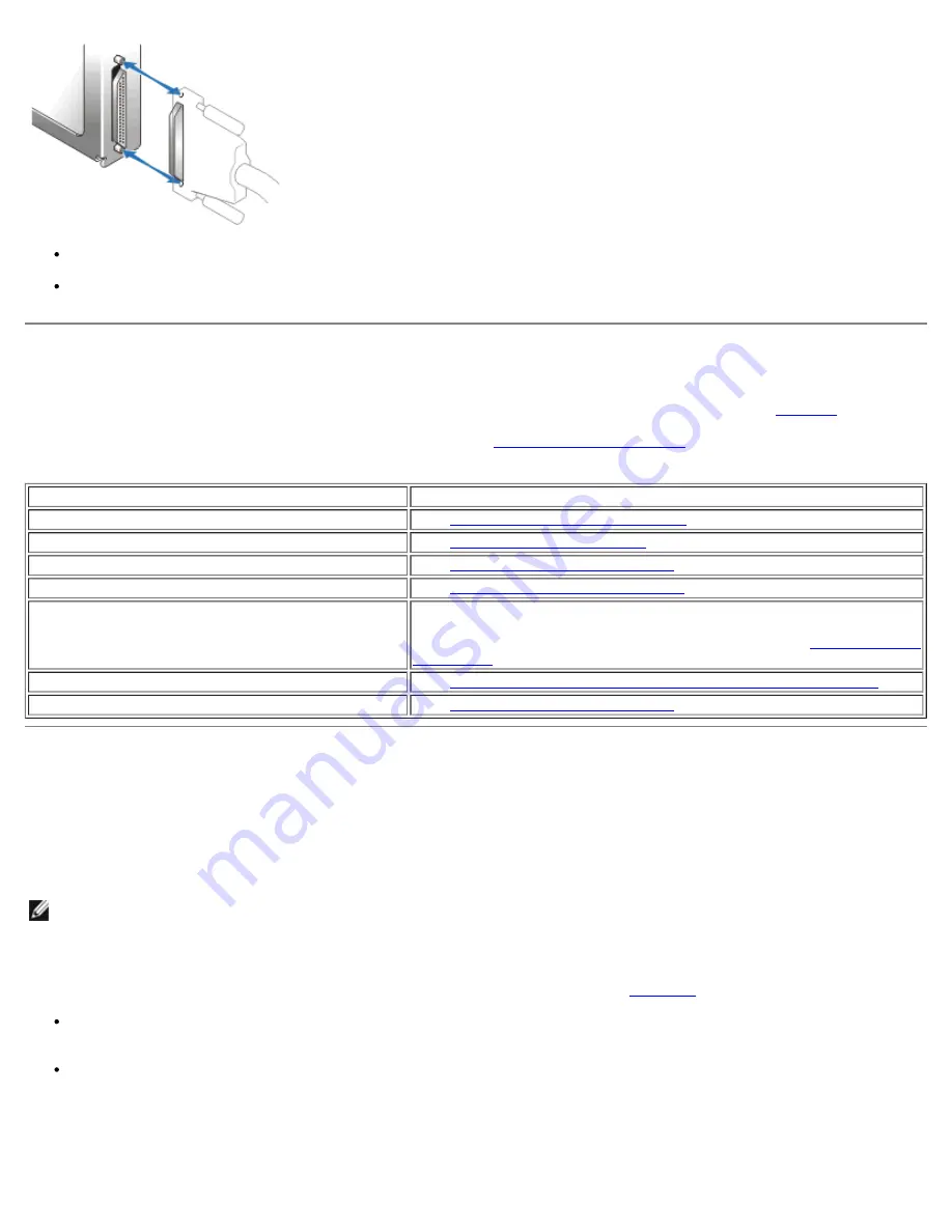
Ensure that the cable connectors are firmly seated before you tighten the captive thumbscrews.

When detaching the cable, avoid damage to the cable by grasping and pulling on the cable connector rather than the

cable. Also, separate the connectors carefully to avoid damage to the connector pins.

Indicators Overview

The LED indicators on your storage system provide valuable information when troubleshooting the system. 

Table 10

 lists the

most common system and component faults and tells you where to look in this section to find more information on correcting

the problem. For locations and descriptions of LED indicators, see "

Components and Indicators

."

Table 10. Common System and Component Faults

Illuminated Indicator

Corrective Action

Drive status LED (drive failure flash pattern)

See "

Troubleshooting SCSI Hard Drives

."

Shelf-fault indicator only

See "

Troubleshooting the System

"

Shelf-fault indicator and power supply fault indicator See "

Troubleshooting a Power Supply

."

Shelf-fault indicator and cooling fan fault indicator

See "

Troubleshooting a Cooling Module

."

Shelf-fault indicator and over-temperature indicator Use your array management software to check the system temperature.

See your array management software documentation for more

information. If a temperature fault is not indicated, see "

Troubleshooting

the System

."

Shelf-fault indicator and EMM fault indicator

See "

Removing and Installing EMMs and the SCSI Terminator Card

."

None

See "

Troubleshooting a Power Supply

."

Troubleshooting SCSI Hard Drives

Hard-drive problems can be caused by a number of conditions, including problems with the drive itself, other electronics in the

system, or an interface cable.

You can resolve many hard-drive problems by validating your SCSI cable connections as described in your 

Installation and

Troubleshooting Guide

.

NOTE:

 Not all SCSI cables are interchangeable. For your storage system to function properly, it is recommended that you

use the cables shipped with the system. If you are using other SCSI cables, they must be approved for U160 or U320 use,

whichever applies to your configuration. The U320 cable can be used in a U160 environment, but the U160 is not usable in

a U320 environment.

In the event of a drive failure event, the status LED indicator on the drive carrier (see 

Figure 11

) flashes the following patterns:

Predicted failure — The status indicator flashes green, then amber, then off, repeating this sequence every two seconds if

a drive is showing signs of imminent failure. 

Drive failure — The status indicator flashes amber four times per second if a drive fails.

Figure 11. Hard Drive Status LED Indicators

1

drive busy LED indicator

2

drive status LED indicator

Содержание PowerVault 220S

Страница 1: ...ner whatsoever without the written permission of Dell Computer Corporation is strictly forbidden Trademarks used in this text Dell the DELL logo PowerVault and Dell OpenManage are trademarks of Dell Computer Corporation IBM is a registered trademark of International Business Machines Corporation Other trademarks and trade names may be used in this document to refer to either the entities claiming ...

Страница 2: ...n on configuring and managing your storage system This manual is divided into the following sections System Overview Overview of the system s features components and technical specifications Basic Troubleshooting Initial checks and procedures used to solve basic system problems Removing and Replacing Parts Removal and replacement of all field replaceable parts including power supplies cooling modu...

Страница 3: ...9 inches Capacity for fourteen 1 inch hot plug SCSI hard drives See Technical Specifications or your system s readme file for supported hard drive speeds and capacities Universal hard drive carriers Support for a variety of RAID controller cards host integrated RAID controllers and host bus adapter HBA cards See your system s readme file for supported RAID controllers and HBA cards Hot plug power ...

Страница 4: ...covers or other components Components and Indicators Front Panel Components and Indicators Figure 1 shows the front view orientation of both systems Figure 1 System Orientation 1 PowerVault 220S 2 PowerVault 221S Figure 2 illustrates LED indicators and components on the system s front panel Table 1 lists conditions indicated by each LED Figure 2 Front Panel Features 1 drive busy LED indicator 2 dr...

Страница 5: ...s the hard drive LED indicators with the associated LED icons Table 3 lists the flash patterns for the hard drive status indicator Table 2 Hard Drive Carrier LED Indicators LED Indicator LED Icon Condition Busy green The hard drive is active on the SCSI bus NOTE This LED is controlled by the hard drive Status green and amber See Table 3 for flash patterns and conditions Table 3 Hard Drive Carrier ...

Страница 6: ...tor card 2 cooling module blowers 2 and 3 3 power supply blank 4 power supply 5 cooling module blowers 0 and 1 6 unused port 7 EMM 8 split bus module Back Panel Modules Figure 5 illustrates the features and indicators on the back panel modules See Figure 6 for more information about bus configuration switch modes Figure 5 Back Panel Modules Features and Indicators 1 bus configuration switch 2 powe...

Страница 7: ...ms left for tower systems The only difference between cluster mode and joined bus mode is the SCSI ID assigned to the enclosure services processor on the EMM When cluster mode is detected the processor SCSI ID changes from 6 to 15 As a result SCSI ID 15 is disabled leaving 13 available hard drives in cluster mode This allows a second initiator such as a host bus adapter or RAID controller card on ...

Страница 8: ...e quality of the SCSI signals and allows longer cable connections Management functions Includes SES and SAFTE reporting to the host system control of all system LED indicators and monitoring of all environmental elements such as temperature sensors cooling modules and power supplies A system with redundant enclosure management features has two EMMs that are designated as primary and secondary that...

Страница 9: ...e power supply is needed a blank must be inserted into the other slot to mount the second cooling module In this nonredundant power supply configuration the power supply blank has the capacity to transfer power and control signals to and from the cooling module If one blower within a cooling module fails your storage system reverts to a nonredundant fan configuration The remaining three blowers in...

Страница 10: ... audible alarm is disabled by default To enable the alarm you must change the default setting using your array management software For more information see your array management software documentation NOTE When the system is on and a split bus module is not detected the audible alarm will sound regardless of whether it is enabled or disabled Table 9 Audible Alarm Critical and Noncritical Events Cr...

Страница 11: ... pin shielded P type SCSI for connection to host Hard drives fourteen 80 pin SCA 2 connectors Power supply cooling module 2 high current connectors Enclosure management modules EMM 210 pin connector Split bus module 180 pin connector Enclosure Modules EMM 2 warm pluggable modules with 68 pin shielded P type SCSI connectors Split bus module 1 warm pluggable module with an external slide switch to c...

Страница 12: ... V Physical Height 13 26 cm 5 22 inches Width 44 58 cm 17 55 inches Depth 50 8 cm 20 inches Weight PowerVault 220S PowerVault 221S 32 4 kg 71 5 lb maximum redundant configuration with all hard drives installed 42 2 kg 93 0 lb maximum redundant configuration with all hard drives installed Environmental Temperature Operating Storage 10 to 35 C 50 to 95 F 40 to 65 C 40 to 149 F Relative humidity Oper...

Страница 13: ...System Overview Dell PowerVault 220S and 221S Systems Service Manual file C Users rishi_sood Desktop 220s en sm intro htm 3 7 2013 12 09 13 PM Back to Contents Page ...

Страница 14: ...owing procedures in the order presented NOTE When you see the question Is the problem resolved in a troubleshooting procedure perform the operation that caused the problem Safety First For You and Your System Do not attempt to service the system except as explained in this guide and elsewhere in Dell documentation Additionally before you service the system review all of the procedures in Safety In...

Страница 15: ...eck the system temperature See your array management software documentation for more information If a temperature fault is not indicated see Troubleshooting the System Shelf fault indicator and EMM fault indicator See Removing and Installing EMMs and the SCSI Terminator Card None See Troubleshooting a Power Supply Troubleshooting SCSI Hard Drives Hard drive problems can be caused by a number of co...

Страница 16: ... No Change either the bus configuration switch mode or cabling between the host and storage system Then reboot the storage system and the host 4 Are the status LED indicators for all the hard drives illuminated Yes End troubleshooting No Go to step 5 5 If a hard drive s status indicator is off reseat the hard drive by removing it from its drive bay and reinstalling it see Removing and Installing H...

Страница 17: ...y For more information see Troubleshooting a Power Supply 5 Is the amber fault indicator for either cooling module blower illuminated See Figure 8 for location No Go to step 6 Yes One of the cooling module blowers has failed Replace the failed module see Replacing a Cooling Module For more information see Troubleshooting a Cooling Module 6 Is the amber fault indicator on an EMM illuminated See Fig...

Страница 18: ...oblem resolved Yes End troubleshooting No Replace the power supply see Replacing the Power Supply Troubleshooting Common Faults and Errors The following section provides procedures for troubleshooting some of the most common faults and errors Shelf Fault Is On With Audible Alarm This section provides a procedure for troubleshooting your system when either a continuous or intermittent audible alarm...

Страница 19: ...een During Host Boot 1 Is the storage system turned off No Go to step 2 Yes Turn on the storage system using the on off switch on the back of the power supply s see Figure 8 for switch location 2 Is the SCSI cable s damaged or not attached securely to the SCSI connectors on the EMM s and the host controller No Go to step 3 Yes Secure the cable s or check connector pins for damage 3 Is the power LE...

Страница 20: ...hat could result in data loss Inspect your SCSI cables for damage Verify that the SCSI IDs on your host system s RAID controller s are set up correctly This is particularly important in a clustered environment Consult your RAID controller documentation for more information Verify that the split bus module switch is set correctly see Split Bus Module and that your system is properly cabled for your...

Страница 21: ... Hard Drives Your storage system features a SCSI backplane that simplifies cabling and configuring your storage system s SCSI hard drives The SCSI backplane configures all SCSI IDs When used in combination with a host RAID controller that supports hot pluggable drives the SCSI backplane allows you to remove and insert hard drives without shutting down the storage system You can replace a failed dr...

Страница 22: ...ze the release mechanism on the front of the hard drive carrier see Figure 12 Figure 12 Installing and Removing Hard Drives 1 chassis face plate 2 carrier guide rail 3 drive carrier handle 4 carrier release mechanism 5 Open the hard drive carrier handle 6 Gently but firmly pull the hard drive carrier from its slot NOTE If the wrong drive is inadvertently removed your array management software issu...

Страница 23: ...4 Figure 14 Configuring a SCSI Drive Carrier 1 pin holes for SCSI configuration labeled S 2 detached drive rail 3 access pins insert from inside the rail d Reassemble the slide rail to the carrier shield and bend the metal retaining tab back into place 2 If you are replacing a hard drive in a carrier perform the following steps to install the new hard drive into the carrier a Remove the four screw...

Страница 24: ...e SCSI Terminator Card A system with redundant enclosure management features two EMMs that are designated as primary and secondary and can be configured in either a cluster or joined bus mode A system with nonredundant enclosure management consists of one EMM and one SCSI terminator card configured in a joined bus mode or two EMMs configured in a split bus mode In redundant EMM systems only one EM...

Страница 25: ...ate the firmware for your EMM s See the Dell Support website at support dell com for the latest information on firmware updates NOTE If you have two EMMs installed both must be running the same firmware level Also both EMMs must be the same speed A label on the EMM identifies whether the module is a U160 or a U320 Removing and Installing the Split Bus Module Your system comes equipped with one war...

Страница 26: ...ver for the changes to take effect For more information see your Installation and Troubleshooting Guide 2 Carefully insert the split bus module into the empty module slot 3 Push the module to the back of the slot until it is firmly seated in the backplane connector see Figure 17 4 Using a 2 Phillips head screwdriver tighten the captive screw at the top of the split bus module to secure the module ...

Страница 27: ... is removed is turned off or unplugged and will decrease when it is removed from the system 1 Turn off the power on the failed power supply and then disconnect the power cable 2 Using a Phillips head screwdriver turn the two captive screws counterclockwise to release the power supply and cooling module from the module bay see Figure 18 Figure 18 Replacing the Power Supply Systems With Redundant Po...

Страница 28: ...d turn on the on off switch 7 Tighten the two captive screws clockwise to secure the new power supply and cooling module in the module bay 8 Connect the AC power cable to the new power supply and to an electrical outlet 9 Turn on the on off switch on the new power supply Replacing a Power Supply in Systems With Nonredundant Power Supplies To replace the power supply in a system that uses only a si...

Страница 29: ...ling module in the module bay 10 Connect the AC power cable to the new power supply and to an electrical outlet 11 Turn on the on off switch on the new power supply Replacing a Cooling Module Your system supports two combined power supply and cooling modules While the system is designed to operate normally with only one functional power supply both cooling modules with two blowers each must be pre...

Страница 30: ...hed to a power supply reattach the power cable and turn on the power supply Replacing the SCSI Backplane The SCSI backplane in your storage system provides an interface for up to fourteen LVD SCSI hard drives two EMMs two combined power supply and cooling modules and one split bus module With the exception of redundant temperature sensors and an EEPROM for storing system data the backplane contain...

Страница 31: ...backplane all the way into the chassis until the two alignment holes at the lower left and top right corners are seated firmly on the two alignment pins 12 Replace chassis tray making sure that the tray is seated on the alignment pins that secure the backplane 13 Replace the screws you removed in step 7 14 Replace the split bus module See Removing and Installing the Split Bus Module 15 Replace the...

Страница 32: ...Removing and Replacing Parts Dell PowerVault 220S and 221S Systems Service Manual file C Users rishi_sood Desktop 220s en sm remove htm 3 7 2013 12 09 15 PM Back to Contents Page ...

Отзывы: