background image

• Provide a suitable power source with electrical overload protection. All Storage Center components 

must be grounded before applying power. Make sure that there is a safe electrical earth connection to 

power supply cords. Check the grounding before applying power.

• The plugs on the power supply cords are used as the main disconnect device. Make sure that the 

socket outlets are located near the equipment and are easily accessible.

• Know the locations of the equipment power switches and the room's emergency power-off switch, 

disconnection switch, or electrical outlet.

• Do not work alone when working with high-voltage components.
• Use rubber mats specifically designed as electrical insulators.
• Do not remove covers from the power supply unit. Disconnect the power connection before 

removing a power supply from the expansion enclosure.

• Do not remove a faulty power supply unless you have a replacement model of the correct type ready 

for insertion. A faulty power supply must be replaced with a fully operational module power supply 

within 24 hours.

• Unplug the storage system chassis before you move it or if you think it has become damaged in any 

way. When powered by multiple AC sources, disconnect all supply power for complete isolation.

Electrostatic Discharge Precautions

Always follow electrostatic discharge (ESD) precautions to avoid injury and damage to Storage Center 

equipment.

Electrostatic discharge (ESD) is generated by two objects with different electrical charges coming into 
contact with each other. The resulting electrical discharge can damage electronic components and 
printed circuit boards. Follow these guidelines to protect your equipment from ESD:

• Dell recommends that you always use a static mat and static strap while working on components in 

the interior of the storage system chassis.

• Observe all conventional ESD precautions when handling plug-in modules and components.
• Use a suitable ESD wrist or ankle strap.
• Avoid contact with backplane components and module connectors.
• Keep all components and printed circuit boards (PCBs) in their antistatic bags until ready for use.

General Safety Precautions

Always follow general safety precautions to avoid injury and damage to Storage Center equipment.

• Keep the area around the expansion enclosure chassis clean and free of clutter.
• Place any system components that have been removed away from the expansion enclosure chassis or 

on a table so that they are not in the way of foot traffic.

• While working on the expansion enclosure chassis, do not wear loose clothing such as neckties and 

unbuttoned shirt sleeves, which can come into contact with electrical circuits or be pulled into a 

cooling fan.

• Remove any jewelry or metal objects from your body because they are excellent metal conductors 

that can create short circuits and harm you if they come into contact with printed circuit boards or 

areas where power is present.

• Do not lift a expansion enclosure chassis by the handles of the power supply units (PSUs). They are 

not designed to hold the weight of the entire chassis, and the chassis cover may become bent.

• Before moving a expansion enclosure chassis, remove the PSUs to minimize weight.
• Do not remove drives until you are ready to replace them.

14

Replacing SC400/SC420 Expansion Enclosure Components

Содержание PowerEdge SC420

Страница 1: ...Dell Storage Center SC400 and SC420 Expansion Enclosure Owner s Manual Regulatory Model E03J E04J Regulatory Type E03J001 E04J001 ...

Страница 2: ... problem WARNING A WARNING indicates a potential for property damage personal injury or death Copyright 2015 Dell Inc All rights reserved This product is protected by U S and international copyright and intellectual property laws Dell and the Dell logo are trademarks of Dell Inc in the United States and or other jurisdictions All other marks and names mentioned herein may be trademarks of their re...

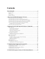
Страница 3: ...nts 13 Safety Precautions 13 Installation Safety Precautions 13 Electrical Safety Precautions 13 Electrostatic Discharge Precautions 14 General Safety Precautions 14 Pre Replacement Procedures 15 Send Diagnostic Data Using Dell SupportAssist 15 Replacing the Front Bezel 15 Replacing Hard Drives 16 SC400 SC420 Expansion Enclosure Drive Numbering 16 Identifying the Failed Hard Drive 16 Replacing a H...

Страница 4: ...Technical Specifications 24 4 ...

Страница 5: ...owing documentation is available for the SC400 SC420 expansion enclosure Dell Storage Center SC400 and SC420 Expansion Enclosure Getting Started Guide Provides information about an SC400 SC420 expansion enclosure such as installation instructions and technical specifications Dell Storage Center Software Update Guide Describes how to update Storage Center software from an earlier version to the cur...

Страница 6: ... to manage a Storage Center Dell Enterprise Manager Administrator s Guide Contains in depth feature configuration and usage information Dell TechCenter Provides technical white papers best practice guides and frequently asked questions about Dell Storage products Go to http en community dell com techcenter storage 6 ...

Страница 7: ...t power supply cooling fan modules and two redundant enclosure management modules EMMs SC400 SC420 Expansion Enclosure Monitoring and Diagnostics The Storage Center OS generates alert messages for temperature I O module fan module disk and power conditions for Storage Center components Use the Dell Storage Client to view these alerts The SC400 SC420 also has LED indicators to notify you of possibl...

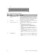
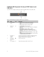
Страница 8: ...to the enclosure 3 Enclosure status LED The enclosure status LED lights when the enclosure power is on Solid blue during normal operation Blinks blue when a host server is identifying the enclosure or when the system identification button is pressed Blinks amber or remains solid amber for a few seconds and then turns off when the EMMs are starting or resetting Blinks amber for an extended time whe...

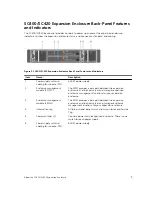
Страница 9: ...The EMM provides a data path between the expansion enclosure and the host server and manages expansion enclosure management functions for your expansion enclosure 3 Enclosure management module EMM 1 The EMM provides a data path between the expansion enclosure and the host server and manages enclosure management functions for your expansion enclosure 4 Information tag A slide out label panel which ...

Страница 10: ... is not properly configured Blinking green Automatic update in progress Blinking amber two times per sequence Expansion enclosure is unable to communicate with other expansion enclosures Blinking amber four times per sequence Firmware update failed Blinking amber five times per sequence Firmware versions are different between the two EMMs 3 SAS ports 1 4 Input or Output Provides SAS connections fo...

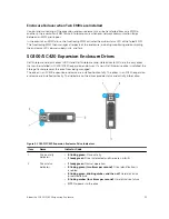
Страница 11: ...d in SC400 SC420 expansion enclosures If a non Dell Enterprise drive is installed the Storage Center prevents the drive from being managed The drives in an SC400 expansion enclosure are installed horizontally The drives in an SC420 expansion enclosure are installed vertically The indicators on the drives provide status and activity information Figure 5 SC400 SC420 Expansion Enclosure Drive Indicat...

Страница 12: ...Item Name Indicator Code 3 Hard disk drive 12 About the SC400 SC420 Expansion Enclosure ...

Страница 13: ... the expansion enclosure is always fully grounded to prevent damage from electrostatic discharge When handling the expansion enclosure hardware use an electrostatic wrist guard not included or a similar form of protection The chassis must be mounted in a rack The following safety requirements must be considered when the chassis is being mounted The rack construction must be capable of supporting t...

Страница 14: ...discharge can damage electronic components and printed circuit boards Follow these guidelines to protect your equipment from ESD Dell recommends that you always use a static mat and static strap while working on components in the interior of the storage system chassis Observe all conventional ESD precautions when handling plug in modules and components Use a suitable ESD wrist or ankle strap Avoid...

Страница 15: ...ront Bezel The front bezel is a cover for the front panel of the expansion enclosure About this task The front bezel must be removed from the front panel when replacing hard drives Steps 1 Use the system key to unlock the keylock at the left end of the bezel 2 Lift the release latch next to the keylock 3 Rotate the left end of the bezel away from the front panel 4 Unhook the right end of the bezel...

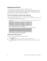
Страница 16: ...identifies drives as XX YY where XX is the unit ID of the expansion enclosure and YY is the drive position inside the expansion enclosure The SC400 holds up to 12 drives which are numbered from left to right in rows starting from 0 at the top left drive Figure 7 SC400 Expansion Enclosure Drive Numbering The SC420 holds up to 24 drives which are numbered from left to right starting from 0 Figure 8 ...

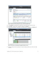
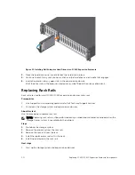
Страница 17: ...tatus of each hard drive is displayed in the Disks tab 6 Select the failed hard drive The location of the failed hard drive is displayed in the Disk View tab Figure 10 Front View of the Enclosure Showing the Failed Hard Drive 7 Optional To open a wizard to guide you through the replacement steps right click on the failed hard drive Replacing SC400 SC420 Expansion Enclosure Components 17 ...
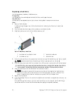
Страница 18: ... the hard drive carrier or the handle 5 Insert the hard drive carrier into the hard drive slot until the carrier make contact with the backplane CAUTION Do not remove the hard drive blanks that are installed in hard drive slots that are not occupied The hard drive blanks ensure proper cooling of the expansion enclosure 6 Close the hard drive carrier handle to lock the hard drive in place NOTE Allo...

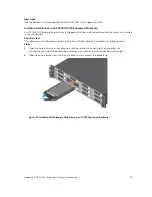
Страница 19: ...tructions describe the installation of Dell Enterprise hard drives for reference only Steps 1 Open the hard drive carrier handle and insert the hard drive carrier into the hard drive slot Start on the left side of the expansion enclosure with slot 0 and install drives from left to right 2 Slide the drive into the slot until the hard drive carrier contacts the backplane Figure 12 Installing Dell En...

Страница 20: ...es into a rack Prerequisites 1 Use SupportAssist to send diagnostic data to Dell Technical Support Services 2 Shut down the storage system and expansion enclosures About this task Use this procedure to replace rack rails NOTE Replacing rack rails must be performed during a scheduled maintenance window when the Storage Center system is unavailable to the network Steps 1 Shut down the storage system...

Страница 21: ...nent of an SC400 SC420 expansion enclosure Send Diagnostic Data Using Dell SupportAssist Use Dell SupportAssist to send diagnostic data to Dell Technical Support Services 1 Click Send SupportAssist Data Now The Send Support Assist Data Now dialog box appears 2 Select Storage Center Configuration and Detailed Logs 3 Click OK Replacing SC400 SC420 Expansion Enclosure Components 21 ...

Страница 22: ...fferent power source Replace the power cord If the DC power LED is not lit verify that the power switch is turned on 3 Reseat the power supply cooling fan module by removing and reinstalling it NOTE Allow several seconds for the expansion enclosure to recognize the power supply cooling fan module and determine its status Troubleshooting Hard Drives Use these steps to troubleshoot hard drives 1 Che...

Страница 23: ...on the expansion enclosure and the storage system c Restart the expansion enclosure and then the storage system d Recheck the link status LEDs If the link status LEDs are not green replace the cables Troubleshooting the Control Panel Use these steps to troubleshoot the control panel 1 Determine the status of the control panel LEDs If the LEDs are not lit and the enclosure is powered on the control...

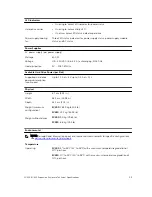
Страница 24: ...t Modules EMMs EMMs Two hot swappable IO modules Connectivity Configurations Storage Center supports up to 960 drives in five redundant path SAS chains An SC9000 supports up to 16 SC400 expansion enclosures or up to 8 SC420 expansion enclosures per chain Redundant Array of Independent Disks RAID Storage System SC9000 Management RAID management using Dell Storage Client 2015 R2 Back Panel Connector...

Страница 25: ...e power consumption continuous Up to 1 2 A at 5 V up to 0 5 A at 12 V Physical Height 8 7 cm 3 43 in Width 48 2 cm 18 98 in Depth 54 1 cm 21 3 in Weight maximum configuration SC400 28 59 kg 63 03 lb SC420 24 2 kg 53 35 lb Weight without drives SC400 9 0 kg 19 84 lb SC420 8 8 kg 19 4 lb Environmental NOTE For additional information about environmental measurements for specific configurations see de...

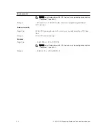
Страница 26: ...0 C per hour Relative humidity Operating 8 to 85 noncondensing with a maximum humidity gradation of 10 per hour Storage 5 to 95 noncondensing Altitude Operating 16 to 3048 m 50 to 10 000 ft NOTE For altitudes above 2950 ft the maximum operating temperature is derated 1 F per 550 ft Storage 16 to 10 600 m 50 to 35 000 ft 26 SC400 SC420 Expansion Enclosure Technical Specifications ...

Отзывы: