background image

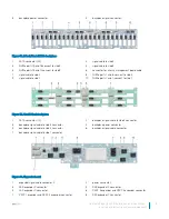
9

SAS expander B connector

10

SAS expander A connector

11

expander signal cable connector 1

Removing the backplane

Prerequisites

CAUTION: 

To prevent damage to the drives and backplane, you must remove the drives from the system before removing the 

backplane.

CAUTION: 

You must note the slot number of each drive and temporarily label them before removal so that you can replace them 

in the same slots.

NOTE: 

Observe the routing of the cables on the chassis as you remove them from the system. You must route these cables 

properly when you replace them to prevent the cables from being pinched or crimped.

1

Follow the safety guidelines listed in 

Safety instructions

.

2

Follow the procedure listed in 

Before working inside your system

.

3

Remove the drive cage.

4

Disconnect all the cables from the backplane.

Steps

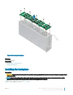
Orient the drive cage so that the drive bays are facing down.

Using the Phillips #2 screwdriver, remove the screws that secure the backplane to the drive cage.

Lift the backplane away from the drive cage.

74

Dell PowerEdge C6400 Installation and Service Manual  
Installing and removing enclosure components

Содержание PowerEdge C6400

Страница 1: ...Dell PowerEdge C6400 Installation and Service Manual Regulatory Model E43S Series Regulatory Type E43S001 ...

Страница 2: ... to hardware or loss of data and tells you how to avoid the problem WARNING A WARNING indicates a potential for property damage personal injury or death Copyright 2017 Dell Inc or its subsidiaries All rights reserved Dell EMC and other trademarks are trademarks of Dell Inc or its subsidiaries Other trademarks may be trademarks of their respective owners 2017 07 Rev A00 ...

Страница 3: ...s 19 Environmental specifications 20 Temperature specifications 20 Relative humidity specifications 20 Maximum vibration specifications 21 Maximum shock specifications 21 Maximum altitude specifications 21 Operating temperature de rating specifications 21 Particulate and gaseous contamination specifications 22 Standard operating temperature specifications 22 Expanded operating temperature specific...

Страница 4: ...poser board 54 Installing the power interposer board 55 Chassis management board 57 Removing the chassis management board 57 Installing the chassis management board 58 Linking board 59 Removing the linking board 59 Installing the linking board 61 Midplane 63 Removing the right midplane 63 Installing the right midplane 64 Removing the left midplane 65 Installing the left midplane 66 Midplane power ...

Страница 5: ...nsor board 84 Installing the thermal sensor board 85 5 Getting help 87 Receiving automated support with SupportAssist 87 Contacting Dell 87 Documentation feedback 88 Accessing system information by using QRL 88 Quick Resource Locator for C6400 and C6420 systems 88 Dell PowerEdge C6400 Installation and Service Manual Contents 5 ...

Страница 6: ...TA drives up to 12 x 3 5 inch SAS or SATA drives diskless no backplane Topics Supported configurations Front view of the PowerEdge C6400 enclosure Front view of the control panels Back view of the PowerEdge C6400 enclosure with PowerEdge C6420 sleds Sled to hard drive mapping Diagnostic indicators Locating the Service Tag of your system Supported configurations The PowerEdge C6400 system supports ...

Страница 7: ...Figure 1 Supported configurations for PowerEdge C6400 Dell PowerEdge C6400 Installation and Service Manual PowerEdge C6400 overview 7 ...

Страница 8: ...x 2 5 inch drives 1 left control panel 2 drive bay 3 right control panel 4 EST tag Figure 3 Front view of the enclosure with 12 x 3 5 inch drives 1 left control panel 2 drive bay 3 right control panel 4 EST tag 8 Dell PowerEdge C6400 Installation and Service Manual PowerEdge C6400 overview ...

Страница 9: ... and 4 are located on the right control panel 3 power on indicator or system state indicator or power button for sleds 1 and 3 Press the power button to turn the sled on or off The power on indicator turns amber when a critical system event occurs NOTE To gracefully shut down an ACPI compliant operating system press the power button 4 system identification button for sleds 1 and 3 Press the system...

Страница 10: ...t down an ACPI compliant operating system press the power button 6 system identification button for sleds 2 and 4 Press the system ID button To locate a particular sled within the enclosure To turn the system ID on or off NOTE If the sled stops responding during POST press and hold the system ID button for more than five seconds to enter the BIOS progress mode Back view of the PowerEdge C6400 encl...

Страница 11: ...3 mapped to sled 4 5 optional NVMe hard drive location Figure 7 Sled to drive mapping for the enclosure with 12 x 3 5 inch drives 1 drives 0 2 mapped to sled 1 2 drives 3 5 mapped to sled 2 3 drives 6 8 mapped to sled 3 4 drives 9 11 mapped to sled 4 NOTE The warranty of the drives are linked to the Service Tag of the corresponding sled Dell PowerEdge C6400 Installation and Service Manual PowerEdg...

Страница 12: ...dicator 3 hard drive NOTE If the hard drive is in the Advanced Host Controller Interface AHCI mode the status LED indicator does not turn on Table 2 Hard drive indicator codes Hard drive status indicator code Condition Flashes green twice per second Identifying drive or preparing for removal Off Drive ready for removal NOTE The drive status indicator remains off until all drives are initialized af...

Страница 13: ...t or received Link indicator is amber and activity indicator is blinking green The NIC is connected to a valid network at less than its maximum port speed and data is being sent or received Link indicator is green and activity indicator is off The NIC is connected to a valid network at its maximum port speed and data is not being sent or received Link indicator is amber and activity indicator is o...

Страница 14: ... same power rating This results in a PSU mismatch condition or failure to turn the system on CAUTION When correcting a PSU mismatch replace only the PSU with the blinking indicator Swapping the PSU to make a matched pair can result in an error condition and unexpected system shutdown To change from a high output configuration to a low output configuration or vice versa you must turn off the system...

Страница 15: ...Figure 11 Locating the Service Tag of your system 1 information tag top view 2 QR code label 3 Express Service Tag label Dell PowerEdge C6400 Installation and Service Manual PowerEdge C6400 overview 15 ...

Страница 16: ...RACADM subcommands and supported RACADM interfaces see the RACADM Command Line Reference Guide for iDRAC Dell com idracmanuals For information about updating drivers and firmware see the Methods to download firmware and drivers section in this document To download drivers Dell com support drivers Managing your system For information about systems management software offered by Dell see the Dell Op...

Страница 17: ...nderstanding the features of the Dell PowerEdge RAID controllers PERC Software RAID controllers or BOSS card and deploying the cards see the Storage controller documentation Dell com storagecontrollermanuals Understanding event and error messages For information about checking the event and error messages generated by the system firmware and agents that monitor system components see the Dell Event...

Страница 18: ... Dimensions of the PowerEdge C6400 enclosure Chassis weight PSU specifications Hard drives and storage specifications Environmental specifications Dimensions of the PowerEdge C6400 enclosure Figure 12 Dimensions of PowerEdge C6400 enclosure 3 18 Dell PowerEdge C6400 Installation and Service Manual Technical specifications ...

Страница 19: ... 240 V AC autoranging 14 A 16 A 2000 W AC Platinum 635 BTU hr 50 60 Hz 100 240 V AC autoranging 11 5 A 1600 W AC Platinum 475 BTU hr 50 60 Hz 100 240 V AC autoranging 10 A NOTE Heat dissipation is calculated using the PSU wattage rating NOTE This system is also designed to connect to the IT power systems with a phase to phase voltage not exceeding 240 V NOTE If a system with 2400 W AC PSU operates...

Страница 20: ...ch PCIe riser of each sled Environmental specifications Temperature specifications Table 10 Temperature specifications Temperature Specifications Storage 40 C to 65 C 40 F to 149 F Continuous operation for altitude less than 950 m or 3117 ft 10 C to 35 C 50 F to 95 F with no direct sunlight on the equipment Fresh air For information about fresh air see Expanded Operating Temperature section Maximu...

Страница 21: ...n the positive and negative x y z axes for up to 2 ms one pulse on each side of the system Maximum altitude specifications Table 14 Maximum altitude specifications Maximum altitude Specifications Operating 3048 m 10 000 ft Storage 12 000 m 39 370 ft Operating temperature de rating specifications Table 15 Operating temperature Operating temperature de rating Specifications Up to 35 C 95 F Maximum t...

Страница 22: ...iquescent point less than 60 relative humidity NOTE This condition applies to data center and non data center environments Table 17 Gaseous contamination specifications Gaseous contamination Specifications Copper coupon corrosion rate 300 Å month per Class G1 as defined by ANSI ISA71 04 1985 Silver coupon corrosion rate 200 Å month as defined by AHSRAE TC9 9 NOTE Maximum corrosive contaminant leve...

Страница 23: ...2 8 Not supported 21 C 69 8 F 21 C 69 8 F 21 C 69 8 F 21 C 69 8 F 30 C 86 F 8180M CPU1 6 CPU2 8 21 C 69 8 F 21 C 69 8 F 21 C 69 8 F 21 C 69 8 F 30 C 86 F 8168 CPU1 6 CPU2 8 21 C 69 8 F 21 C 69 8 F 21 C 69 8 F 21 C 69 8 F 30 C 86 F 200W 6154 CPU1 6 CPU2 8 Not supported 22 C 71 6 F 22 C 71 6 F 22 C 71 6 F 22 C 71 6 F 30 C 86 F 165W 6150 CPU1 8 CPU2 8 Not supported 30 C 86 F 30 C 86 F 30 C 86 F 35 C ...

Страница 24: ...8 CPU2 8 30 C 86 F 30 C 86 F 30 C 86 F 30 C 86 F 30 C 86 F 35 C 95 F 35 C 95 F 8160 CPU1 8 CPU2 8 30 C 86 F 30 C 86 F 30 C 86 F 30 C 86 F 30 C 86 F 35 C 95 F 35 C 95 F 8160T CPU1 6 CPU2 8 30 C 86 F 30 C 86 F 30 C 86 F 30 C 86 F 30 C 86 F 35 C 95 F 35 C 95 F 140W 6132 CPU1 8 CPU2 8 Not supported 30 C 86 F 30 C 86 F 30 C 86 F 30 C 86 F 30 C 86 F 35 C 95 F 35 C 95 F 6152 CPU1 8 CPU2 8 30 C 86 F 30 C ...

Страница 25: ... 30 C 86 F 30 C 86 F 30 C 86 F 35 C 95 F 35 C 95 F 35 C 95 F 35 C 95 F 35 C 95 F 115W 6128 CPU1 6 CPU2 8 25 C 77 F 30 C 86 F 30 C 86 F 30 C 86 F 30 C 86 F 35 C 95 F 35 C 95 F 35 C 95 F 35 C 95 F 35 C 95 F 105W 8156 CPU1 6 CPU2 8 30 C 86 F 35 C 95 F 35 C 95 F 35 C 95 F 35 C 95 F 35 C 95 F 35 C 95 F 35 C 95 F 35 C 95 F 35 C 95 F 5122 CPU1 6 CPU2 8 30 C 86 F 35 C 95 F 35 C 95 F 35 C 95 F 35 C 95 F 35...

Страница 26: ...5 C 95 F 35 C 95 F 35 C 95 F 35 C 95 F 5119T CPU1 8 CPU2 8 35 C 95 F 35 C 95 F 35 C 95 F 35 C 95 F 35 C 95 F 35 C 95 F 35 C 95 F 35 C 95 F 35 C 95 F 35 C 95 F 4117T CPU1 8 CPU2 8 35 C 95 F 35 C 95 F 35 C 95 F 35 C 95 F 35 C 95 F 35 C 95 F 35 C 95 F 35 C 95 F 35 C 95 F 35 C 95 F 4115T CPU1 8 CPU2 8 35 C 95 F 35 C 95 F 35 C 95 F 35 C 95 F 35 C 95 F 35 C 95 F 35 C 95 F 35 C 95 F 35 C 95 F 35 C 95 F 7...

Страница 27: ... model number Max DIMM count per CPU 12x 3 5 HDDs enclosur e 8x 3 5 HDDs enclosur e 4x 3 5 HDDs enclosur e 24x 2 5 HDDs enclosur e 20x 2 5 HDDs enclosur e 16x 2 5 HDDs enclosur e 12x 2 5 HDDs enclosur e 8x 2 5 HDDs enclosur e 4x 2 5 HDDs enclosur e No back plane enclosur e 205W 8180 CPU1 6 30 C 86 F 30 C 86 F 30 C 86 F 35 C 95 F 35 C 95 F 35 C 95 F 35 C 95 F 35 C 95 F 35 C 95 F 35 C 95 F 8180M CPU...

Страница 28: ... 35 C 95 F 35 C 95 F 35 C 95 F 35 C 95 F 35 C 95 F 35 C 95 F 35 C 95 F 35 C 95 F 35 C 95 F 8164 CPU1 8 30 C 86 F 35 C 95 F 35 C 95 F 35 C 95 F 35 C 95 F 35 C 95 F 35 C 95 F 35 C 95 F 35 C 95 F 35 C 95 F 8160M CPU1 8 30 C 86 F 35 C 95 F 35 C 95 F 35 C 95 F 35 C 95 F 35 C 95 F 35 C 95 F 35 C 95 F 35 C 95 F 35 C 95 F 8160 CPU1 8 30 C 86 F 35 C 95 F 35 C 95 F 35 C 95 F 35 C 95 F 35 C 95 F 35 C 95 F 35...

Страница 29: ... C 86 F 35 C 95 F 35 C 95 F 35 C 95 F 35 C 95 F 35 C 95 F 35 C 95 F 35 C 95 F 35 C 95 F 35 C 95 F 5122 CPU1 6 30 C 86 F 35 C 95 F 35 C 95 F 35 C 95 F 35 C 95 F 35 C 95 F 35 C 95 F 35 C 95 F 35 C 95 F 35 C 95 F 5120 CPU1 8 35 C 95 F 35 C 95 F 35 C 95 F 35 C 95 F 35 C 95 F 35 C 95 F 35 C 95 F 35 C 95 F 35 C 95 F 35 C 95 F 5118 CPU1 8 35 C 95 F 35 C 95 F 35 C 95 F 35 C 95 F 35 C 95 F 35 C 95 F 35 C 9...

Страница 30: ...35 C 95 F 35 C 95 F 35 C 95 F 35 C 95 F 35 C 95 F 35 C 95 F 70W 4109T CPU1 8 35 C 95 F 35 C 95 F 35 C 95 F 35 C 95 F 35 C 95 F 35 C 95 F 35 C 95 F 35 C 95 F 35 C 95 F 35 C 95 F Table 22 Maximum continuous operating temperature for fabric single processor configuration TDP W Process or model number Max DIMM count per CPU 12x 3 5 HDDs enclosur e 8x 3 5 HDDs enclosur e 4x 3 5 HDDs enclosur e 24x 2 5 ...

Страница 31: ...erating in the expanded temperature range system performance may be impacted NOTE When operating in the expanded temperature range ambient temperature warnings may be reported in the System Event Log Fresh Air Operation Fresh Air operation restrictions Processors with a TDP greater than 105 W are not supported Support for processors of 85 W and below without PERC restrictions 3 5 HDD configuration...

Страница 32: ... antistatic strap while working on components inside the system CAUTION To ensure proper operation and cooling all bays in the system and system fans must be always populated with a component or a blank Before working inside your system Prerequisites Follow the safety guidelines listed in Safety instructions Steps 1 Turn off the system including any attached peripherals 2 Disconnect the system fro...

Страница 33: ...TION This system must be operated with the system cover installed to ensure proper cooling Figure 13 Inside the C6400 enclosure 1 sled 4 2 right midplane 3 fan cage 2 4 fan 4 5 right linking board 6 backplane 7 drive cage 8 expander board 9 left midplane 10 left linking board 11 chassis management board 12 power interposer board Dell PowerEdge C6400 Installation and Service Manual Installing and r...

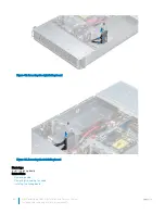
Страница 34: ...dge C6400 enclosure The sled features dual processors memory a PCIe expansion slot mezzanine cards and onboard storage SD card and M 2 SATA Removing a sled Prerequisites 1 Follow the safety guidelines listed in Safety instructions 2 Follow the procedure listed in Before working inside your system NOTE The process of removing a sled blank is similar to removing a sled Steps Press the retaining latc...

Страница 35: ...Figure 15 Removing a sled Dell PowerEdge C6400 Installation and Service Manual Installing and removing enclosure components 35 ...
Страница 36: ... ensure proper cooling of the system Related links Installing a sled Installing a sled Prerequisites 1 Follow the safety guidelines listed in Safety instructions 2 If installed remove the sled blank Steps Slide the sled into the enclosure until it locks into place 36 Dell PowerEdge C6400 Installation and Service Manual Installing and removing enclosure components ...
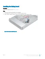
Страница 37: ...Figure 17 Installing a sled Dell PowerEdge C6400 Installation and Service Manual Installing and removing enclosure components 37 ...

Страница 38: ...ocumentation for the storage controller card to ensure that the host adapter is configured correctly CAUTION Do not turn off or restart your system while a hard drive is being formatted Doing so can cause a hard drive failure When you format a hard drive allow enough time for the formatting to complete Be aware that high capacity hard drives can take a long time to format Removing a hard drive Pre...

Страница 39: ...s 1 Press the release button to open the hard drive release handle 2 Holding the handle slide the hard drive out of the hard drive slot Figure 19 Removing a hard drive Next steps 1 Install a hard drive 2 If you are not replacing the hard drive immediately insert a hard drive blank in the empty hard drive slot to maintain proper system cooling Related links Installing a hard drive Installing a hard...

Страница 40: ...pplicable remove the hard drive blank Steps 1 Press the release button on the front of the hard drive to open the release handle 2 Insert the hard drive into the hard drive slot and slide until the hard drive connects with the backplane 3 Close the hard drive release handle to lock the hard drive in place Figure 20 Installing a hard drive Removing a hard drive blank The procedure for removing 2 5 ...

Страница 41: ... hard drive blanks from previous generations of PowerEdge servers is not supported Steps Insert the hard drive blank into the hard drive slot and push until the release button clicks into place Figure 22 Installing a hard drive blank Next steps 1 Follow the procedure listed in After working inside your system Removing the hard drive from the hard drive carrier Prerequisites Follow the safety guide...

Страница 42: ...arrier Prerequisites Follow the safety guidelines listed in Safety instructions CAUTION Mixing hard drives from previous generations of PowerEdge servers is not supported Steps 1 Insert the hard drive into the hard drive carrier with the connector end of the hard drive towards the back of the carrier 2 Align the screw holes on the hard drive with the screws holes on the hard drive carrier When ali...

Страница 43: ... PSUs NOTE For more information see the Technical specifications section Removing a power supply unit Prerequisites 1 Follow the safety guidelines listed in Safety instructions 2 Disconnect the power cable from the power source and from the PSU you intend to remove and then remove the cable from the strap on the PSU handle 3 Unlatch and lift the optional cable management arm if it interferes with ...

Страница 44: ...ctions 2 For systems that support redundant PSU ensure that both the PSUs are of the same type and have the same maximum output power NOTE The maximum output power shown in watts is listed on the PSU label Steps Slide the PSU into the system until the PSU is fully seated and the release latch snaps into place 44 Dell PowerEdge C6400 Installation and Service Manual Installing and removing enclosure...

Страница 45: ...is discovered and enabled before you remove the other PSU The PSU status indicator turns green to signify that the PSU is functioning properly System cover System cover provides security for the entire system and also helps in maintaining proper air flow inside the system Removing the system cover Prerequisites 1 Follow the safety guidelines listed in Safety instructions 2 Turn off each sled in th...

Страница 46: ...ct documentation or as directed by the online or telephone service and support team Damage due to servicing that is not authorized by Dell is not covered by your warranty Read and follow the safety instructions that are shipped with your product Follow the safety guidelines listed in Safety instructions Steps Place the system cover on the chassis and slide it to the front of the chassis until it l...

Страница 47: ...nclosures with the 3 5 inch hard drive configuration 1 Follow the safety guidelines listed in Safety instructions 2 Follow the procedure listed in Before working inside your system Steps 1 Using the Phillips 1 screwdriver remove the screws that secure the backplane cover to the enclosure 2 Slide the backplane cover toward the back of the enclosure and lift the cover away Dell PowerEdge C6400 Insta...

Страница 48: ... guidelines listed in Safety instructions Steps 1 Align the screw holes on the backplane cover with the screw holes on the chassis by sliding the cover toward the front of the enclosure 2 Using the Phillips 1 screwdriver tighten the screws to secure the backplane cover to the enclosure 48 Dell PowerEdge C6400 Installation and Service Manual Installing and removing enclosure components ...
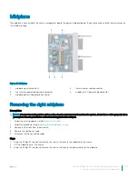
Страница 49: ...es Removing a cooling fan Prerequisites WARNING Do not attempt to operate the system without the cooling fans WARNING The cooling fan spins for some time after the system is powered down Allow the fan to stop spinning before removing it from the system 1 Follow the safety guidelines listed in Safety instructions 2 Follow the procedure listed in Before working inside your system Steps Disconnect th...

Страница 50: ...alling a cooling fan Prerequisites 1 Follow the safety guidelines listed in Safety instructions Steps 1 Align the cooling fan with the fan slot on the cooling fan cage and push the cooling fan until it is firmly seated 2 Connect the fan cable to the connector on the cooling fan cage 50 Dell PowerEdge C6400 Installation and Service Manual Installing and removing enclosure components ...
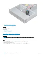
Страница 51: ...to stop spinning before removing it from the system NOTE Observe the routing of the cables when removing them from the system Route these cables properly when you replace them to prevent the cables from being pinched or crimped 1 Follow the safety guidelines listed in Safety instructions 2 Follow the procedure listed in Before working inside your system 3 Remove the cooling fans Steps 1 Disconnect...

Страница 52: ...erly when you replace them to prevent the cables from being pinched or crimped Follow the safety guidelines listed in Safety instructions Steps 1 Align the guide pins on the cooling fan cage with the guide holes on the chassis 2 Install the fan cage onto the chassis and push until it is firmly seated on the guide holes 3 Connect the fan power cable to the connector on the chassis management board ...

Страница 53: ...ur system 3 Check the management software to see if all the fans are rotating at the optimal speed Related links Installing a cooling fan Power interposer board Figure 35 Power interposer board 1 backplane power connector 2 release lever Dell PowerEdge C6400 Installation and Service Manual Installing and removing enclosure components 53 ...

Страница 54: ...ontact surfaces of the connectors 1 Follow the safety guidelines listed in Safety instructions 2 Follow the procedure listed in Before working inside your system 3 Remove the power supply units 4 Disconnect all the cables from the PIB except for the midplane power cables Steps 1 To release the PIB from the lock on the chassis pull the blue release latch 2 Holding the release latch lift the PIB up ...

Страница 55: ...w the power interposer board PIB to discharge after you power off the system Handle the PIB by the edges and avoid touching the contact surfaces of the connectors 1 Follow the safety guidelines listed in Safety instructions Steps 1 Using the Phillips 2 screwdriver replace the screws that secure the midplane power cable to the PIB Dell PowerEdge C6400 Installation and Service Manual Installing and ...

Страница 56: ...PIB 2 Align and insert the PIB on the guide hooks on the chassis 3 Push the PIB down to secure it with the lock on the chassis Figure 39 Installing the PIB 56 Dell PowerEdge C6400 Installation and Service Manual Installing and removing enclosure components ...
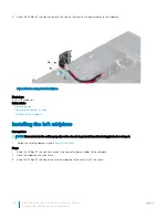
Страница 57: ...rom PIB 5 chassis management board signal cable to PIB 6 FPGA connector 7 MCU connector 8 COM connector 9 firmware jumpers 10 right midplane signal cable 11 fan cage 2 connector for fans 3 and 4 Removing the chassis management board Prerequisites 1 Follow the safety guidelines listed in Safety instructions 2 Follow the procedure listed in Before working inside your system 3 Remove the power supply...

Страница 58: ...e power interposer board Installing the chassis management board Installing the chassis management board Prerequisites Follow the safety guidelines listed in Safety instructions Steps 1 Insert the chassis management board into the enclosure aligning the guide slots with the standoffs on the chassis 2 Push the board toward the back of the enclosure to align the screw holes on the board and standoff...

Страница 59: ...e sled to the allotted drives on the backplane Removing the linking board Prerequisites 1 Follow the safety guidelines listed in Safety instructions 2 Follow the procedure listed in Before working inside your system 3 Remove the sleds from the enclosure 4 Remove the fan cage Steps 1 Using the Phillips 1 screwdriver remove the screw that secures the linking board to the enclosure 2 Lift the linking...

Страница 60: ...moving the left linking board Next steps Install the linking board Related links Removing a sled Removing the cooling fan cage Installing the linking board 60 Dell PowerEdge C6400 Installation and Service Manual Installing and removing enclosure components ...

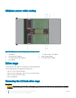
Страница 61: ...to the linking board 2 Align the board with the standoff on the chassis and slide the board into place 3 Using a Phillips 1 screwdriver replace the screw on the linking board to secure the board in place Figure 45 Installing the right linking board Dell PowerEdge C6400 Installation and Service Manual Installing and removing enclosure components 61 ...
Страница 62: ...cage 2 Install the sleds into the enclosure 3 Follow the procedure listed in After working inside your system Related links Installing the cooling fan cage Installing a sled 62 Dell PowerEdge C6400 Installation and Service Manual Installing and removing enclosure components ...
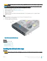
Страница 63: ...e system Route these cables properly when you replace them to prevent the cables from being pinched or crimped 1 Follow the safety guidelines listed in Safety instructions 2 Follow the procedure listed in Before working inside your system 3 Remove all the sleds from the enclosure 4 Remove the cooling fan cage 5 Disconnect all the connected cables Steps 1 Using the Phillips 1 screwdriver remove the...

Страница 64: ...y on the chassis to prevent them from being pinched or crimped 1 Follow the safety guidelines listed in Safety instructions Steps 1 Using the Phillips 1 screwdriver connect and secure the power cables to the midplane 2 Place the midplane into the chassis 3 Using the Phillips 1 screwdriver tighten the screws that secure the midplane to the chassis 64 Dell PowerEdge C6400 Installation and Service Ma...

Страница 65: ...ove them from the system Route these cables properly when you replace them to prevent the cables from being pinched or crimped 1 Follow the safety guidelines listed in Safety instructions 2 Follow the procedure listed in Before working inside your system 3 Remove all the sleds from the enclosure 4 Remove the cooling fan cage 5 Disconnect all the connected cables Steps 1 Using the Phillips 1 screwd...

Страница 66: ...requisites NOTE You must route the cables properly on the chassis to prevent them from being pinched or crimped 1 Follow the safety guidelines listed in Safety instructions Steps 1 Using the Phillips 1 screwdriver connect and secure the power cables to the midplane 2 Place the midplane into the chassis 3 Using the Phillips 1 screwdriver secure the midplane to the chassis with the screws 66 Dell Po...

Страница 67: ...stall the cooling fan cage 3 Install the sleds into the enclosure 4 Follow the procedure listed in After working inside your system Related links Installing the cooling fan cage Installing a sled Dell PowerEdge C6400 Installation and Service Manual Installing and removing enclosure components 67 ...
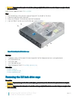
Страница 68: ...he backplane and the expander board The drive cage supports the following drive configurations up to 24 x 2 5 inch SAS or SATA drives up to 8 x 2 5 inch NVMe drives with 16 x 2 5 inch SAS or SATA drives up to 12 x 3 5 inch SAS or SATA drives diskless no backplane Removing the 2 5 inch drive cage Prerequisites CAUTION To prevent damage to the drives and backplane you must remove the drives from the...

Страница 69: ... board cables from the linking board and chassis management board 6 Remove all the drives Steps 1 Using the Phillips 1 screwdriver remove the screws that secure the drive cage to the chassis 2 Slide the drive cage to the unlock position 3 Lift the drive cage away from the enclosure Figure 53 Removing the 2 5 inch drive cage Next steps Install the 2 5 inch drive cage Related links Removing the back...

Страница 70: ...e reconnect all the cables that were disconnected from the linking board and chassis management board 2 Install the removed drives 3 Install the fan cages 4 Install the backplane cover 5 Follow the procedure listed in After working inside your system Related links Installing a hard drive Installing the cooling fan cage Installing the backplane cover Removing the 3 5 inch drive cage Prerequisites C...

Страница 71: ...drive cage to the unlock position 3 Hold and lift the drive cage up 4 Lift the drive cage away from the enclosure Figure 55 Removing the 3 5 inch drive cage Next steps Install the 3 5 inch drive cage Related links Removing the cooling fan cage Removing a hard drive Installing the 3 5 inch drive cage Installing the 3 5 inch drive cage Prerequisites CAUTION To prevent damage to the drives and backpl...

Страница 72: ...ll the backplane cables that were disconnected from the linking board and chassis management board 2 Install all the removed drives 3 Install the fan cages 4 Follow the procedure listed in After working inside your system Related links Installing a hard drive Installing the cooling fan cage Backplanes and expander board Figure 57 24 x 2 5 inch backplane 1 SATA connector 24 2 expander power connect...

Страница 73: ...kplane 1 SATA connector 12 2 backplane signal cable to sled 4 connector 3 backplane signal cable to sled 3 connector 4 backplane power connector 5 backplane signal cable to sled 2 connector 6 backplane signal cable connector 7 backplane signal cable to sled 1 connector Figure 60 Expander board 1 expander signal cable connector 2 2 power connector 3 SAS expander F connector 4 SAS expander E connect...

Страница 74: ... you remove them from the system You must route these cables properly when you replace them to prevent the cables from being pinched or crimped 1 Follow the safety guidelines listed in Safety instructions 2 Follow the procedure listed in Before working inside your system 3 Remove the drive cage 4 Disconnect all the cables from the backplane Steps 1 Orient the drive cage so that the drive bays are ...

Страница 75: ...rarily label them before removal so that you can replace them in the same slots NOTE Observe the routing of the cables on the chassis as you remove them from the system You must route these cables properly when you replace them to prevent the cables from being pinched or crimped Follow the safety guidelines listed in Safety instructions Dell PowerEdge C6400 Installation and Service Manual Installi...

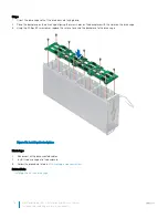
Страница 76: ...driver replace the screws to secure the backplane to the drive cage Figure 62 Installing the backplane Next steps 1 Reconnect all the disconnected cables 2 Install the drive cage into the enclosure 3 Follow the procedure listed in After working inside your system Related links Installing the 2 5 inch drive cage 76 Dell PowerEdge C6400 Installation and Service Manual Installing and removing enclosu...

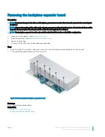
Страница 77: ...on 1 Follow the safety guidelines listed in Safety instructions 2 Follow the procedure listed in Before working inside your system 3 Remove the drive cage 4 Disconnect all the cables from the backplane expander board Steps 1 Using the Phillips 2 screwdriver remove the screws that secure the backplane expander board to the drive cage 2 Lift the backplane expander board out of the enclosure Figure 6...

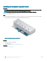
Страница 78: ...ted in Safety instructions Steps 1 Install the backplane expander board into the enclosure aligning the screw holes on the board with the holes on the drive cage 2 Using the Phillips 2 screwdriver secure the backplane expander board to the chassis Figure 64 Installing the backplane expander board Next steps 1 Reconnect all the disconnected cables 2 Install the drive cage 3 Follow the procedure lis...

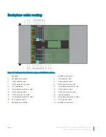
Страница 79: ...ing board 10 linking board connector for sled 1 11 linking board connector for sled 2 12 NVMe cable for sled 3 13 NVMe cable for sled 4 14 NVMe connector for sled 4 15 NVMe connector for sled 3 16 right linking board 17 linking board connector for sled 3 18 linking board connector for sled 4 19 SATA cable for sled 3 20 SATA cable for sled 4 21 backplane signal cable 3 22 backplane signal cable 4 D...

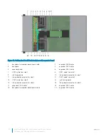
Страница 80: ...left linking board 10 linking board connector for sled 1 11 linking board connector for sled 2 12 PERC cable from sled 4 13 PERC cable from sled 3 14 right linking board 15 linking board connector for sled 3 16 linking board connector for sled 4 17 expander SAS E cable 18 expander SAS F cable 19 backplane to expander board power cable 20 expander SAS D cable 80 Dell PowerEdge C6400 Installation an...

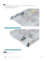
Страница 81: ...ing the control panel Prerequisites NOTE Observe the routing of the cables on the enclosure as you remove them You must route these cables properly when you replace them to prevent the cables from being pinched or crimped 1 Follow the safety guidelines listed in Safety instructions 2 Follow the procedure listed in Before working inside your system 3 Remove all the drives 4 Disconnect all the backp...

Страница 82: ...e cable from the cable retention clips 3 Lift the control panel assembly away Figure 68 Removing the left control panel assembly Figure 69 Removing the right control panel assembly Next steps Install the control panel assembly 82 Dell PowerEdge C6400 Installation and Service Manual Installing and removing enclosure components ...
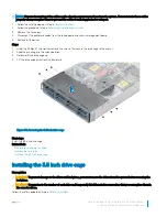
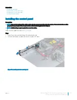
Страница 83: ...es properly when you replace them to prevent the cables from being pinched or crimped NOTE Additional tape maybe required to secure the cables Follow the safety guidelines listed in Safety instructions Steps 1 Route the control panel cable through the cable retention clips 2 Install the control panel assembly and secure it in place with screws Figure 70 Installing the left control panel Dell Power...

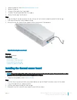
Страница 84: ...re around the enclosure Removing the thermal sensor board Prerequisites CAUTION To prevent damage to the drives and backplane you must remove the drives from the system before removing the backplane CAUTION You must note the number of each drive and temporarily label them before removal so that you can replace them in the same locations NOTE Observe the routing of the cables on the chassis as you ...

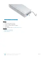
Страница 85: ...emoving the 2 5 inch drive cage Removing the 3 5 inch drive cage Installing the thermal sensor board Installing the thermal sensor board Prerequisites NOTE Observe the routing of the cables on the chassis as you remove them from the system You must route these cables properly on the chassis to prevent them from being pinched or crimped 1 Follow the safety guidelines listed in Safety instructions S...

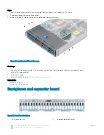
Страница 86: ... Connect the control panel cables to the midplane 4 Install the drives 5 Follow the procedure listed in After working inside your system Related links Installing the 2 5 inch drive cage Installing the 3 5 inch drive cage Installing a hard drive 86 Dell PowerEdge C6400 Installation and Service Manual Installing and removing enclosure components ...
Страница 87: ...nding on the Dell Service entitlement purchased for your device For more information about SupportAssist go to Dell com SupportAssist Contacting Dell Dell provides several online and telephone based support and service options If you do not have an active internet connection you can find contact information about your purchase invoice packing slip bill or Dell product catalog Availability varies b...

Страница 88: ...ocated on the system Information tag Prerequisites Ensure that your smart phone or tablet has the QR code scanner installed The QRL includes the following information about your system How to videos Reference materials including the Owner s Manual and mechanical overview A direct link to Dell to contact technical assistance and sales teams Steps 1 Go to Dell com QRL and navigate to your specific p...

Отзывы: