Steps
1. Loosen the three captive screws (M1.6x2) that secure the display-assembly cable bracket to the system board.
2. Lift the display-assembly cable bracket off the system board.
3. Disconnect the camera cable and the display cable from the system board.
4. Remove the three screws (M1.2x2) that secure the display-assembly cable holder to the palm-rest and keyboard assembly.
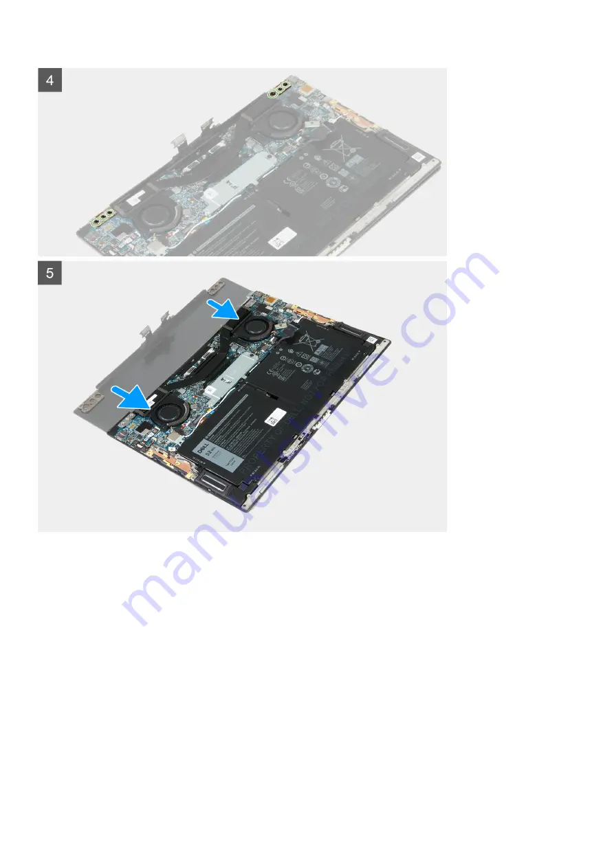
5. Remove the three screws (M2.5x4.5) that secure the left hinge to the system board and the palm-rest and keyboard
assembly.
6. Remove the three screws (M2.5x4.5) that secure the right hinge to the system board and the palm-rest and keyboard
assembly.
7. Slide the palm-rest and keyboard assembly from the display assembly.
8. After performing all the above steps, you are left with display assembly.
30
Removing and installing components
Содержание P117G
Страница 1: ...XPS 13 9310 Service Manual Regulatory Model P117G Regulatory Type P117G002 September 2020 Rev A00 ...
Страница 12: ...12 Removing and installing components ...
Страница 29: ...Removing and installing components 29 ...
Страница 32: ...32 Removing and installing components ...
Страница 35: ...Removing and installing components 35 ...
Страница 38: ...38 Removing and installing components ...


