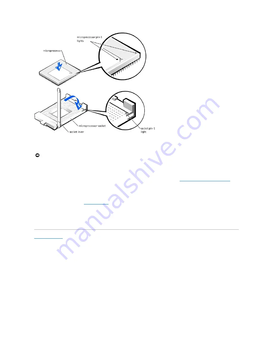
background image


2.


Install the microprocessor heat sink:  


a.


Lower the heat sink to the microprocessor so that the heat sink fits in the heat sink retention base.  


b.


For each of the replacement metal clips that secure the heat sink to the microprocessor, fit the end of the clip that does not have the latch to the heat sink 

retention base. Then, press down on the clip's latch to secure the clip to the heat sink retention base (see "

Removing the Microprocessor Heat Sink

").  


3.


Replace the airflow shroud.  


4.


Rotate the power supply back into position until the securing tab snaps into the release latch.  


5.


Replace the computer cover and 

restart the computer

.  


6.


Enter system setup, and confirm that the top line in the 

System Data

 area correctly identifies the new microprocessor. Also, confirm that the values under the 

CPU Information

 menu are correct for the new microprocessor.  


7.


Exit system setup, and then run the Dell Diagnostics to verify that the new microprocessor is operating properly.  


Back to Contents Page


NOTICE: 

If you are installing a microprocessor upgrade kit from Dell, remove the plastic cover that is attached to the bottom of the new heat sink before 

installing it. 

Содержание OptiPlex GX400

Страница 1: ...ver without the written permission of Dell Computer Corporation is strictly forbidden Trademarks used in this text Dell OptiPlex and the DELL logo are trademarks of Dell Computer Corporation Other trademarks and trade names may be used in this document to refer to either the entities claiming the marks and names or their products Dell Computer Corporation disclaims any proprietary interest in trad...

Страница 2: ... 5 seconds and then remove the computer cover 2 Remove the screw that secures the AGP card brace to the chassis Removing the AGP Card Brace 3 Rotate the brace up until the tab disengages from the card guide at the front of the chassis Then lift the brace away from the chassis Replacing the AGP Card Brace To replace the AGP card brace perform the removal procedure in reverse Back to Contents Page N...

Страница 3: ...ide labeled facing up see Removing the Computer Battery Then insert the battery into the socket and snap it into place 2 Replace the computer cover and restart the computer 3 Enter system setup and enter the current time and date Then exit system setup and save the information Back to Contents Page CAUTION There is a danger of the new battery exploding if it is installed incorrectly Replace the ba...

Страница 4: ...charge from your body before touching anything inside the computer While you work periodically touch an unpainted metal surface on the computer chassis to dissipate any static electricity that might harm internal components Also avoid touching components or contacts on a card and avoid touching pins on a chip 5 Verify that the standby power light on the system board is not on If it is on you may n...

Страница 5: ...e chassis intrusion switch cable from the control panel connector ALERT To locate this connector see Control Panel Components 8 Slide the chassis intrusion switch up out of its slot on the chassis 9 Lift the chassis intrusion switch and switch cable away from the chassis Removing the Chassis Intrusion Switch Replacing the Chassis Intrusion Switch To replace the chassis intrusion switch perform the...

Страница 6: ...Back to Contents Page ...

Страница 7: ...rive bracket 6 Remove the expansion card guide 7 Remove the chassis intrusion switch 8 Remove the screw that secures the control panel 9 Pull the control panel out slightly and unplug the control panel cable 10 To remove the control panel cable a Pull the control panel connector inside the chassis through the opening b Disconnect the control panel cable from the connector on the system board and l...

Страница 8: ...Replacing the Control Panel To replace the control panel perform the removal procedure in reverse Back to Contents Page ...

Страница 9: ...tom of the cover outward away from the chassis d Lift the cover away from the chassis e Lay the computer down on its right side before you begin working inside the chassis Replacing the Computer Cover 1 Check all cable connections and fold cables out of the way so that they do not catch on the computer cover Ensure that cables are not routed over the drive cage they will prevent the cover from clo...

Страница 10: ...ith both hands press against the bottom edge of the cover to ensure that the securing hooks at the bottom of the cover click into place Replacing the Cover c Slide the two parts of the padlock ring together to lock the cover release mechanism Back to Contents Page ...

Страница 11: ... and devices disconnect them from their electrical outlets wait at least 5 seconds and then remove the computer cover 2 Rotate the power supply away from the system board 3 Remove the front panel 4 Disconnect the DC power and interface cables from the back of the drive CAUTION Before you perform this procedure see Precautionary Measures NOTICE Before disconnecting a device from the computer or rem...

Страница 12: ...of Removing the Floppy Drive 2 Slide the drive assembly into the chassis until the green floppy drive bracket release button snaps securely into place See Removing the Floppy Drive Bracket 3 Connect the interface cable for the drive To locate this connector see System Board Components 4 Connect a DC power cable to the power input connector on the back of the drive 5 Ensure that all cables are firm...

Страница 13: ...e together the metal bracket tabs that extend from each side of the drive bracket and pull the bracket out of the bay Removing a Drive Bracket 6 Remove the drive from the bracket Turn the drive bracket assembly upside down and remove the four screws that secure the drive to the bracket Removing the Drive from the Bracket CAUTION Before you perform this procedure see Precautionary Measures NOTICE B...

Страница 14: ...rom the Bracket To further ensure proper positioning of the drive in the chassis insert and tighten all four screws in the order in which the holes are numbered the holes are marked 1 through 4 2 Slide the new drive bracket assembly into the drive bay until both drive bracket tabs snap securely into place Installing the Drive Bracket 3 Connect the interface cable for the drive See Attaching Drive ...

Страница 15: ...to the release latch 9 Replace the computer cover and restart the computer 10 If the drive you installed is a hard drive enter system setup and update the drive settings After you update the system settings exit system setup and reboot the computer 11 If the device you installed is a hard drive partition and logically format the drive before proceeding to the next step See the operating system s d...

Страница 16: ... of the chassis using the metal tab Grasp the hard drive bracket and pull it out of the chassis Removing the Hard Drive Bracket 6 Remove the screw s that secures the drive in the bracket 7 Remove the drive from the bracket Removing a Hard Drive from the Bracket CAUTION Before you perform this procedure see Precautionary Measures NOTICE Before disconnecting a device from the computer or removing a ...

Страница 17: ...rt the drive bracket into the chassis and rotate the bracket until the tabs snap into place Installing the Hard Drive Bracket 4 Connect the interface cable for the drive See Attaching Hard Drive Cables a If you are installing an EIDE device ensure that the IDE interface cable is properly connected to the EIDE connector on the system board NOTE Orient the drive in the bracket so that its bottom wil...

Страница 18: ...control panel system board connector see System Board Components 8 Replace the front panel 9 Rotate the power supply back into position until the securing tab snaps into the release latch 10 Replace the computer cover and restart the computer 11 Enter system setup and update the drive settings After you update the system settings exit system setup and reboot the computer 12 Partition and logically...

Страница 19: ......

Страница 20: ...5 seconds and then remove the computer cover 2 Lay the computer on its right side 3 Remove the AGP card brace If you have an AGP card clip disconnect any cables attached to the card and press the AGP card clip lever toward the expansion card cage AGP Card Clip CAUTION Before you perform this procedure see Precautionary Measures NOTICE Before disconnecting a device from the computer or removing a c...

Страница 21: ... removed in step 5 If you need a filler bracket contact Dell See the User s Guide for information on contacting Dell 9 If you removed the AGP brace replace it If you released the AGP card clip push the lever so that the lever is out of the way while you install a new card or filler bracket Release the lever when the card or filler bracket is installed 10 Stand the computer upright 11 Replace the c...

Страница 22: ... you removed an add in network adapter perform the following steps a Enter system setup select Integrated Devices and change the setting for Network Interface Card to On b Connect the network cable to the integrated network adapter connector on the back panel Back to Contents Page ...

Страница 23: ...b from the chassis b Rotate the released side of the card guide away from the front chassis wall c With the released side of the card guide away from the chassis wall pull the card guide up away from the chassis Removing the Expansion Card Guide Replacing the Expansion Card Guide Insert the two bottom tabs in the slots in the chassis wall Then rotate the card guide toward the front chassis wall un...

Страница 24: ...Back to Contents Page ...

Страница 25: ...button marked with the icon Removing the Front Panel 3 While pressing the front panel release button rotate the top of the panel outward away from the chassis 4 Lift the panel away from the chassis Replacing the Front Panel Fit the two front panel retaining hooks into the recessed slots at the bottom of the chassis See Removing the Front Panel Then rotate the top of the panel toward the chassis un...

Страница 26: ...er and reset buttons by using a small screwdriver to push in the plastic clips that secure the button to the computer cover When these clips are released the button comes free from the front panel Removing Front Panel Buttons Replacing Front Panel Buttons Replace the front panel buttons l To replace the power button insert the button into the hole in the front panel of the computer cover so that t...

Страница 27: ......

Страница 28: ...ont panel 3 Hold the front panel with the front facing you 4 Remove the front panel insert for the chassis drive bay you want to use Use your thumbs to press the sides of the insert until it snaps free of the front panel Removing Front Panel Inserts Replacing Front Panel Inserts Position the two ring tabs over the posts on the inside of the bay opening and then press the ring tabs over the posts S...

Страница 29: ...Interior Chassis Interior Chassis Interior Back to Contents Page NOTE Before you remove the cover you must first slide the outer padlock ring to the left to unlock the cover release mechanism See Cover Release Mechanism NOTE Your computer may have an AGP clip instead of an AGP card brace ...

Страница 30: ... Press the securing clips at each end of the socket outward until they snap open b Align the slots on the bottom of the memory module with the two ridges inside the socket c Press the memory module straight down into the socket until the securing clips snap into place at the ends of the module Installing a Memory Module CAUTION Before you perform this procedure see Precautionary Measures CAUTION R...

Страница 31: ...ility 5 Enter system setup and check the value for System Memory The computer should have already changed the value of System Memory to reflect the newly installed memory If the new total is correct skip to step 7 6 If the memory total is incorrect repeat step 1 and step 3 of Removing a Memory Module Check the installed modules to ensure that they are seated properly in their sockets Then repeat s...

Страница 32: ...e handle that secures or releases the microprocessor CAUTION Before you perform this procedure see Precautionary Measures NOTICE Before disconnecting a device from the computer or removing a component from the board verify that the standby power light on the system board has turned off To locate this light see System Board Components NOTE If you are installing a microprocessor upgrade kit from Del...

Страница 33: ...the socket lever back toward the socket until it snaps into place securing the microprocessor Replacing the Microprocessor NOTICE Do not reuse the old heat sink assembly when replacing the microprocessor package Doing so can cause the microprocessor to overheat because of an inadequate amount of thermal compound between the heat sink assembly and the microprocessor package NOTICE When you place th...

Страница 34: ...oud 4 Rotate the power supply back into position until the securing tab snaps into the release latch 5 Replace the computer cover and restart the computer 6 Enter system setup and confirm that the top line in the System Data area correctly identifies the new microprocessor Also confirm that the values under the CPU Information menu are correct for the new microprocessor 7 Exit system setup and the...

Страница 35: ...tor on the system board FAN To locate this connector see System Board Components 5 Gently pull the plastic locking tab back and slide the fan toward the system board Removing the Microprocessor Cooling Fan 6 Lift the fan out of the chassis Replacing the Microprocessor Cooling Fan To replace the microprocessor cooling fan perform the removal procedure in reverse Back to Contents Page CAUTION Before...

Страница 36: ......

Страница 37: ...by pulling back the release tabs of the shroud and lifting the shroud up until the anchor tabs disengage from the chassis frame See Removing the Airflow Shroud Then lift the airflow shroud out of the chassis Removing the Airflow Shroud Replacing the Microprocessor Airflow Shroud To replace the microprocessor airflow shroud perform the removal procedure in reverse Back to Contents Page CAUTION Befo...

Страница 38: ...e the power supply from the securing tab by pressing the tab labeled RELEASE Then rotate the power supply upward until it locks in its extended position Rotating the Power Supply Removing the Power Supply 1 Rotate the power supply away from the system board 2 Disconnect the power supply cables from all drives 3 Disconnect the power supply cables from the system board 4 Lift the front of the power ...

Страница 39: ... left side of the power supply in the retention arm socket 3 Rotate the right side of the power supply toward the chassis The pivot pin on the right rear of the power supply inserts into the chassis slot See Removing the Power Supply 4 Connect the power supply cables to the system board 5 Connect the power supply cables to all drives 6 Rotate the power supply back into position until the securing ...

Страница 40: ...roprocessor 9 Remove the microprocessor cooling fan 10 Disconnect all cables from the system board 11 Slide all drive brackets partially out of the chassis 12 Remove the screw that secures the system board to the bottom of the chassis 13 Slide the system board toward the front of the chassis until it stops This unlocks the system board 14 Lift the front of the system board 15 Lift the system board...

Страница 41: ...ystem board mounting screw 5 Replace all components on the system board by performing step 3 through step 11 of Removing the System Board in reverse 6 Set the jumpers on the new system board so that they are identical to those on the original board 7 Replace the computer cover and restart the computer 8 Run system setup to ensure that your settings are correct and that all system board components ...

Страница 42: ...els Connector or Component Label AGP AGP connector AUX_LED Auxiliary hard drive access light connector BATTERY Battery socket CD_IN CD audio input connector CPU_POWER Microprocessor power connector DS1 Diagnostic lights DSKT Floppy drive connector FAN Microprocessor fan connector IDE1 Primary EIDE connector IDE2 Secondary EIDE connector KYBD PS 2 keyboard connector ...

Страница 43: ...or POWER Computer power connector PSWD Password jumper RIMM_n RIMM socket RTCRST Real time clock reset jumper SER Serial port connectors SPKR Internal speaker STANDBY_LED Standby power light STR Suspend to RAMlight TAPI Telephony connector USB Port 2 USB connectors 2 USB2 Port 1 USB connectors 2 VRM VRM connector NOTICE Ensure that your computer is turned off before you change a jumper setting Oth...

Страница 44: ...Back to Contents Page ...

Страница 45: ...e NOTE A NOTE indicates important information that helps you make better use of your computer NOTICE A NOTICE indicates either potential damage to hardware or loss of data and tells you how to avoid the problem CAUTION A CAUTION indicates a potentially hazardous situation which if not avoided may result in minor or moderate injury ...

Страница 46: ... the bottom of the new VRM with the ridge inside the connector 2 Press the VRM straight into the connector 3 Replace the VRM securing clip a Lower the clip onto the VRM so that the top corners of the VRM go through the slots in the clip b Press down on the two raised points of the clip s top surface to secure it to the VRM connector see Removing the VRM 4 Rotate the power supply back into position...

Страница 47: ...Back to Contents Page ...

Отзывы: