background image

Drive Cage

16

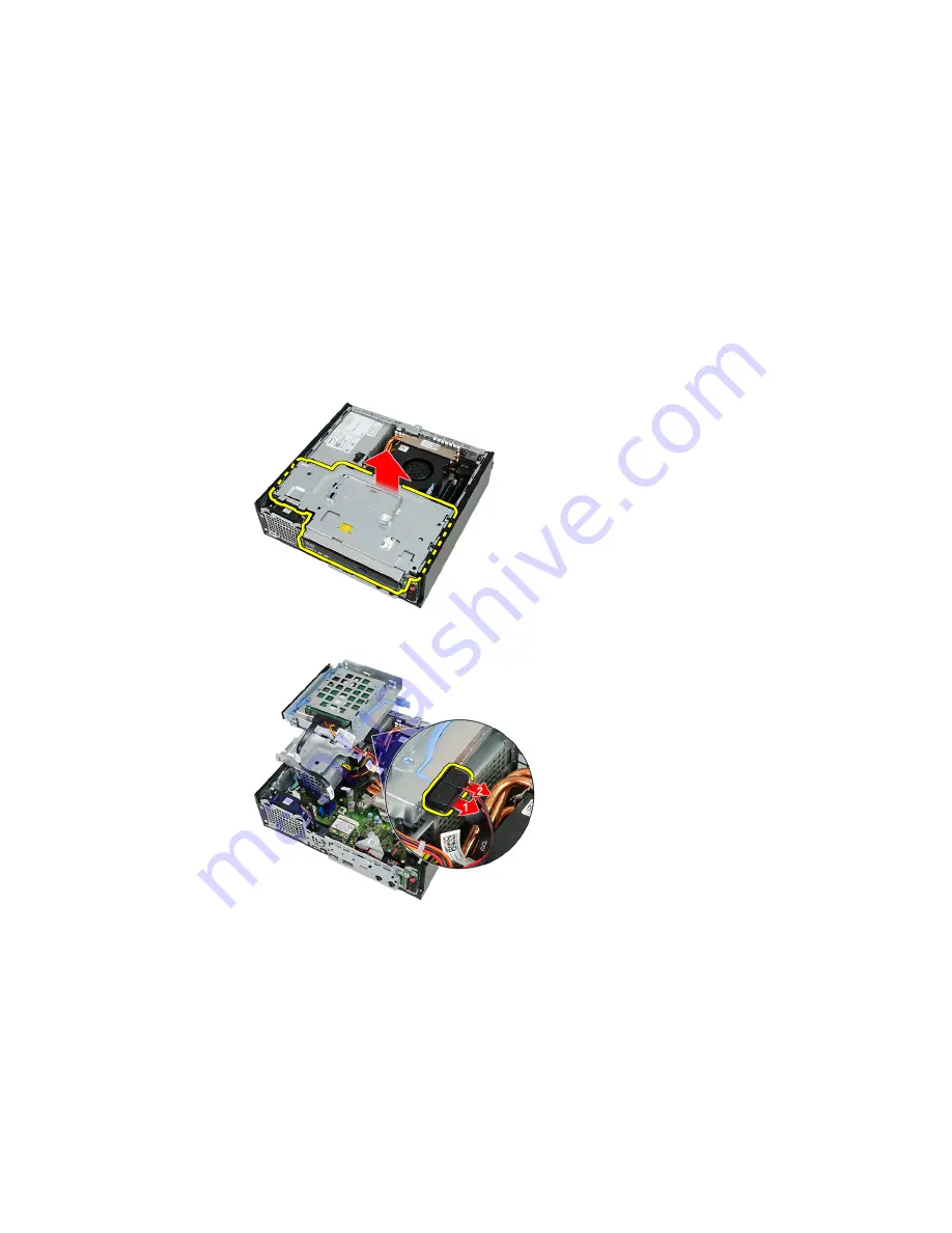
Removing the Drive Cage

1. Follow the procedures in 

Before Working Inside Your Computer

.

2. Remove the 

cover

.

3. Remove the 

front bezel

.

4. Lift the drive cage using the handle and flip over the drive cage.

5. Remove the data cable and power cable from the back of the optical drive.

6. Remove the data cable and power cable from the back of the hard drive.

43

Содержание OptiPlex 990 Desktop

Страница 1: ...Dell OptiPlex 990 Ultra Small Form Factor Service Manual Regulatory Model D01U Regulatory Type D01U001 ...

Страница 2: ...ks of Intel Corporation in the U S and other countries AMD is a registered trademark and AMD Opteron AMD Phenom AMD Sempron AMD Athlon ATI Radeon and ATI FirePro are trademarks of Advanced Micro Devices Inc Microsoft Windows MS DOS Windows Vista the Windows Vista start button and Office Outlook are either trademarks or registered trademarks of Microsoft Corporation in the United States and or othe...

Страница 3: ...Removing the Cover 11 Installing The Cover 12 3 Front Bezel 13 Removing the Front Bezel 13 Installing The Front Bezel 14 4 Optical Drive 15 Removing the Optical Drive 15 Installing The Optical Drive 16 5 Hard Drive 17 Removing the Hard Drive 17 Installing the Hard Drive 18 6 Memory 19 Removing the Memory 19 Installing The Memory 20 7 Chassis Intrusion Switch 21 Removing the Chassis Intrusion Switc...

Страница 4: ...ing The Processor 30 11 Coin Cell Battery 31 Removing the Coin Cell Battery 31 Installing The Coin Cell Battery 32 12 Chassis Fan 33 Removing the System Fan 33 Installing The System Fan 34 13 Input Output Panel 35 Removing the Input Output Board 35 Installing the Input Output Board 36 14 Power Supply 37 Removing the Power Supply 37 Installing The Power Supply 38 15 System Board 39 Removing the Sys...

Страница 5: ...talling The Control Panel 48 19 Internal Antenna 49 Removing the Internal Antenna 49 Installing The Internal Antenna 50 20 System Setup 51 System Setup 51 Boot Menu 51 Boot Menu Enhancements 51 Timing Key Sequences 52 Beep Codes and Text Error Messages 53 Navigation 53 System Setup Options 53 21 Troubleshooting 65 Diagnostic LEDs 65 Beep Codes 72 Error Messages 75 22 Specifications 83 Technical Sp...

Страница 6: ...23 Contacting Dell 93 Contacting Dell 93 ...

Страница 7: ... service and support team Damage due to servicing that is not authorized by Dell is not covered by your warranty Read and follow the safety instructions that came with the product CAUTION To avoid electrostatic discharge ground yourself by using a wrist grounding strap or by periodically touching an unpainted metal surface such as a connector on the back of the computer CAUTION Handle components a...

Страница 8: ...er is unplugged to ground the system board 6 Remove the cover CAUTION Before touching anything inside your computer ground yourself by touching an unpainted metal surface such as the metal at the back of the computer While you work periodically touch an unpainted metal surface to dissipate static electricity which could harm internal components Recommended Tools The procedures in this document may...

Страница 9: ...g system press and hold the power button for about 6 seconds to turn them off After Working Inside Your Computer After you complete any replacement procedure ensure you connect any external devices cards and cables before turning on your computer 1 Replace the cover CAUTION To connect a network cable first plug the cable into the network device and then plug it into the computer 2 Connect any tele...

Страница 10: ...10 ...

Страница 11: ...ver 1 Follow the procedures in Before Working Inside Your Computer 2 Loosen the thumb screw that secures the computer cover 3 Slide the cover towards the back of the computer 4 Lift the cover up and away from the computer 11 ...

Страница 12: ...omputer cover on the chassis 2 Slide the computer cover towards the front of the chassis until it clicks into place 3 Tighten the thumb screw to secure the computer cover 4 Follow the procedures in After Working Inside Your Computer 12 ...

Страница 13: ...the procedures in Before Working Inside Your Computer 2 Remove the cover 3 Pry the front bezel retention clips away from the chassis 4 Rotate the bezel away from the computer to release the hooks on the opposite edge of the bezel from the chassis 13 ...

Страница 14: ...ottom edge of the front bezel into the slots on the chassis front 2 Rotate the bezel toward the computer to engage the front bezel retention clips until they click into place 3 Install the cover 4 Follow the procedures in After Working Inside Your Computer 14 ...

Страница 15: ...e 1 Follow the procedures in Before Working Inside Your Computer 2 Remove the cover 3 Remove the front bezel 4 Remove the drive cage 5 Release the retention clip and remove the optical drive from its cage 6 Remove the optical drive bracket 15 ...

Страница 16: ... 1 Fix the optical drive bracket to the optical drive 2 Secure the optical drive into its cage 3 Install the drive cage 4 Install the front bezel 5 Install the cover 6 Follow the procedures in After Working Inside Your Computer 16 ...

Страница 17: ... Working Inside Your Computer 2 Remove the cover 3 Remove the front bezel 4 Remove the drive cage 5 Remove the hard drive cage from the compartment 6 Remove the screws that secure the hard drive to the drive cage 7 Slide the hard drive to release it from the drive cage 17 ...

Страница 18: ...e hard drive back into the drive cage 2 Tighten the screws to secure the hard drive to the drive cage 3 Install the drive cage 4 Install the front bezel 5 Install the cover 6 Follow the procedures in After Working Inside Your Computer 18 ...

Страница 19: ...efore Working Inside Your Computer 2 Remove the cover 3 Remove the front bezel 4 Remove the drive cage 5 Press out on the release tabs located on each side of the memory module 6 Lift the memory module out of the connector on the system board and remove it 19 ...

Страница 20: ...e connector on the system board 2 Press down on the memory module until the release tabs spring back to secure it in place 3 Install the drive cage 4 Install the front bezel 5 Install the cover 6 Follow the procedures in After Working Inside Your Computer 20 ...

Страница 21: ...n Switch 1 Follow the procedures in Before Working Inside Your Computer 2 Remove the cover 3 Remove the front bezel 4 Remove the drive cage 5 Disconnect the intrusion cable from system board 6 Slide the intrusion switch over and remove it off the bracket 21 ...

Страница 22: ...n switch into the bracket on the power supply and slide it over to secure it 2 Connect the intrusion cable to the system board 3 Install the drive cage 4 Install the front bezel 5 Install the cover 6 Follow the procedures in After Working Inside Your Computer 22 ...

Страница 23: ...omputer 2 Remove the cover 3 Remove the front bezel 4 Remove the drive cage 5 Disconnect the speaker cable from the system board 6 Pull out the speaker cable from beneath the system fan cable and wireless local Area network WLAN antennae if installed 7 Release the latch and rotate the speaker 23 ...

Страница 24: ...d rotate until the latch is secured in place 2 Route the speaker cable beneath the system fan cable and wireless local area network WLAN antennae if installed 3 Connect the speaker cable to the system board 4 Install the drive cage 5 Install the front bezel 6 Install the cover 7 Follow the procedures in After Working Inside Your Computer 24 ...

Страница 25: ...our Computer 2 Remove the cover 3 Remove the front bezel 4 Remove the drive cage 5 Disconnect the heat sink fan assembly cable from the system board 6 Press the release lever down and move it outward to release the fan retention hook that secures it 7 Raise the heat sink fan assembly 25 ...

Страница 26: ...rews to secure the heat sink fan assembly to the system board 9 Lift the heat sink fan assembly upward and remove it from the computer Lay the assembly with the fan facing downward and with the thermal grease facing upward 26 ...

Страница 27: ... the system board 3 Lower the heat sink fan assembly 4 Press the release lever down and then move it inward to secure it with the fan retention hook 5 Connect the heat sink fan assembly cable to the system board 6 Install the drive cage 7 Install the front bezel 8 Install the cover 9 Follow the procedures in After Working Inside Your Computer 27 ...

Страница 28: ...28 ...

Страница 29: ...the cover 3 Remove the front bezel 4 Remove the drive cage 5 Remove the heat sink 6 Press the release lever down Then move it outward to release it from the retention hook that secures it 7 Raise the processor cover 8 Lift the processor to remove it from the socket and place it into an antistatic packaging 29 ...

Страница 30: ...s properly seated 2 Lower the processor cover 3 Press the release lever down and then move it inward to secure it with the retention hook 4 Install the heat sink 5 Install the drive cage 6 Install the front bezel 7 Install the cover 8 Follow the procedures in After Working Inside Your Computer 30 ...

Страница 31: ... Inside Your Computer 2 Remove the cover 3 Remove the front bezel 4 Remove the drive cage 5 Remove the heat sink 6 Press the release latch away from the battery to allow the battery to pop up from the socket 7 Lift the coin cell battery out of the computer and properly dispose of the battery 31 ...

Страница 32: ...on the system board 2 Press the coin cell battery downward until the release latch springs back into place to secure it 3 Install the heat sink 4 Install the drive cage 5 Install the front bezel 6 Install the cover 7 Follow the procedures in After Working Inside Your Computer 32 ...

Страница 33: ...Before Working Inside Your Computer 2 Remove the cover 3 Remove the front bezel 4 Remove the drive cage 5 Disconnect the system fan cable from the system board 6 Disengage the system fan cable from the chassis 7 Remove the screws that secure the fan to the chassis 33 ...

Страница 34: ... chassis 2 Tighten the screws to secure the system fan to the chassis 3 Thread the system fan cable into the chassis clip 4 Connect the system fan cable to the system board 5 Install the drive cage 6 Install the front bezel 7 Install the cover 8 Follow the procedures in After Working Inside Your Computer 34 ...

Страница 35: ...r Computer 2 Remove the cover 3 Remove the front bezel 4 Remove the drive cage 5 Disconnect the Input Output board cable from the system board 6 Remove the screws that secure the Input Output bracket 7 Remove the Input Output bracket from the chassis 8 Remove the screws that secure the Input Output board 35 ...

Страница 36: ...ecuring the Input Output board 2 Insert the Input Output bracket into the slot on the chassis front 3 Tighten the screws to secure the Input Output bracket 4 Connect the Input Output board data cable to the system board 5 Install the drive cage 6 Install the front bezel 7 Install the cover 8 Follow the procedures in After Working Inside Your Computer 36 ...

Страница 37: ...uter 2 Remove the cover 3 Remove the front bezel 4 Remove the drive cage 5 Remove the intrusion switch 6 Remove the heat sink 7 Disconnect the cables from the system board 8 Remove the screw that secures the power supply to the chassis 9 Remove the screws that secure the power supply to the chassis 37 ...

Страница 38: ...is and slide it outward to secure it 2 Tighten screws to secure the power supply to the chassis 3 Connect the cables to the system board 4 Install the heat sink 5 Install the intrusion switch 6 Install the drive cage 7 Install the front bezel 8 Install the cover 9 Follow the procedures in After Working Inside Your Computer 38 ...

Страница 39: ...bezel 4 Remove the drive cage 5 Remove the power supply 6 Remove the heat sink 7 Remove the memory 8 Remove the input output panel 9 Remove the wireless module 10 Remove the speaker 11 Disconnect all the cables connected to the system board and move the cables away from the chassis 12 Unthread and move the internal antenna from the chassis 39 ...

Страница 40: ...13 Remove the screws that secure the system board to the chassis 14 Remove the 7 mm hex screw from the system board 15 Slide the system board towards the front of the computer 40 ...

Страница 41: ...16 Remove the system board from the chassis 41 ...

Страница 42: ...read the internal antenna into the chassis clips 5 Connect the SATA cables hard optical drive power cable system fan cable and the control panel cable to the system board 6 Install the internal speaker 7 Install the wireless module 8 Install the front Input Output panel 9 Install the memory 10 Install the heat sink 11 Install the power supply 12 Install the drive cage 13 Install the front bezel 14...

Страница 43: ...Inside Your Computer 2 Remove the cover 3 Remove the front bezel 4 Lift the drive cage using the handle and flip over the drive cage 5 Remove the data cable and power cable from the back of the optical drive 6 Remove the data cable and power cable from the back of the hard drive 43 ...

Страница 44: ...rive 2 Connect the data cable and power cable to the back of the hard drive 3 Connect the data cable and power cable to the back of the optical drive 4 Flip over the drive cage and insert it into the chassis The drive cage shoulder screws are secured by the slots in the chassis 5 Install the front bezel 6 Install the cover 7 Follow the procedures in After Working Inside Your Computer 44 ...

Страница 45: ...rocedures in Before Working Inside Your Computer 2 Remove the cover 3 Remove the front bezel 4 Remove the drive cage 5 Disconnect the cables from the wireless local area network WLAN card 6 Push the securing levers away from the WLAN card 7 Remove the WLAN card 45 ...

Страница 46: ...s slot 2 Press the WLAN card downward until it is locked in place by the securing levers 3 Connect the antennae according to the color code on the WLAN card 4 Install the drive cage 5 Install the front bezel 6 Install the cover 7 Follow the procedures in After Working Inside Your Computer 46 ...

Страница 47: ...side Your Computer 2 Remove the cover 3 Remove the front bezel 4 Remove the drive cage 5 Remove the memory 6 Disconnect the control panel cable from the system board 7 Unthread the control panel speaker cable from the chassis clip 8 Remove the screw that secures the control panel board 47 ...

Страница 48: ...t 2 Tighten the screw to secure the control panel board 3 Thread the control panel speaker cable into the chassis clip 4 Connect the control panel cable to the system board 5 Install the memory 6 Install the drive cage 7 Install the front bezel 8 Install the cover 9 Follow the procedures in After Working Inside Your Computer 48 ...

Страница 49: ...he procedures in Before Working Inside Your Computer 2 Remove the cover 3 Remove the front bezel 4 Remove the drive cage 5 Disconnect the cables from the wireless local area network WLAN card 6 Unthread the internal antenna 7 Release the internal antenna port 49 ...

Страница 50: ...in the chassis and slide toward the right to secure it 2 Thread the internal antenna into the chassis clip 3 Connect the cables to the wireless local area network WLAN card 4 Install the drive cage 5 Install the front bezel 6 Install the cover 7 Follow the procedures in After Working Inside Your Computer 50 ...

Страница 51: ...e boot and diagnostics utility menu Boot Menu Enhancements The boot menu enhancements are as follows Easier access Although the Ctrl Alt F8 keystroke still exists and can be used to call up the menu simply press F12 during system boot to access the menu User prompting Not only is the menu easy to access when you are prompted to use the keystroke on the BIOS splash screen see image below The keystr...

Страница 52: ...e keyboard When this happens a keyboard error message appears on the monitor and you cannot restart the system with the Ctrl Alt Del keys To avoid this scenario wait until the keyboard is initialized before pressing the keystroke There are two ways to know that this has happened The keyboard lights flash The F2 Setup prompt appears in the top right hand corner of the screen during boot The second ...

Страница 53: ...the BIOS screens Action Keystroke Expand and collapse field Enter left or right arrow key or Expand or collapse all fields Exit BIOS Esc Remain in Setup Save Exit Discard Exit Change a setting Left or right arrow key Select field to change Enter Cancel modification Esc Reset defaults Alt F or Load Defaults menu option System Setup Options NOTE Depending on the computer and its installed devices th...

Страница 54: ...ou to specify the order in which the computer attempts to find an operating system The options are Diskette drive USB Storage Device CD DVD CD RW Drive Onboard NIC SATA CD DVD CD RW Drive Boot List Option Legacy UEFI Date Time Allows you to set the date and time Changes to the system date and time take effect immediately System Configuration Integrated NIC Allows you to enable or disable the integ...

Страница 55: ... enable or disable the various on board drives SATA 0 SATA 1 SATA 2 SATA 3 Smart Reporting This field controls whether hard drive errors for integrated drives are reported during system startup This technology is part of the SMART Self Monitoring Analysis and Reporting Technology specification This option is disabled by default USB Configuration This field configures the integrated USB controller ...

Страница 56: ...This option is disabled by default NOTE The Video setting will only be visible when a video card is installed in the system Security Internal HDD 1 Password Allows you to set change or delete the password on the system s internal hard disk drive HDD Successful changes to this password take effect immediately By default the drive will not have a password set Enter the old password Enter the new pas...

Страница 57: ...hen an administrator password is set Allow Non Admin Password Changes This option is enabled by default Non Admin Setup Changes This option lets you determine whether changes to the setup option are permitted when an administrator password is set Allow Wireless Switch Changes This option is disabled by default TPM Security This option lets you control whether the Trusted Platform Module TPM in the...

Страница 58: ...ation screens via the hotkey One Time Enable User may enter OROM configuration screens via the hotkeys on next boot only After next boot the setting will revert to disabled Disable User may not enter OROM configuration screens via the hotkey This option is set to Enable by default Admin Setup Lockout Allows you to enable or disable the option to enter Setup when an Admin password is set This optio...

Страница 59: ...pplied after a power loss You can set the AC Recovery to Power Off default Power On Last State Auto On Time Allows you to set the option to automatically turn on the computer Time is kept in standard 12 hour format hour minutes seconds Change the startup time by typing the values in the time and AM PM fields NOTE This feature does not work if you turn off your computer using the switch on a power ...

Страница 60: ...fault Keyboard Errors Allows you to enable or disable the keyboard error reporting when the computer starts This option is enabled by default POST Hotkeys Allows you to specify the function keys to display on the screen when the computer starts Enable F12 Boot menu enabled by default Fast Boot This option can speed up the boot process by bypassing some compatibility steps Minimal The system boots ...

Страница 61: ...mechanism This option is not set by default Some graphics cards require that the SERR message mechanism be disabled Image Server Lookup Method Specifies how the ImageServer looks up the server address Static IP DNS enabled by default NOTE This field is only relevant when the Integrated NIC control in the System Configuration group is set to Enabled with ImageServer ImageServer IP Specifies the pri...

Страница 62: ...uration group is set to Enabled with ImageServer and when Client DHCP is set to Static IP Client Subnet Mask Specifies the subnet mask of the client The default setting is 255 255 255 255 NOTE This field is only relevant when the Integrated NIC control in the System Configuration group is set to Enabled with ImageServer and when Client DHCP is set to Static IP Client Gateway Specifies the gateway ...

Страница 63: ...ents Displays the DellDiag event log Thermal Events Displays the thermal event log and allows you to Clear Log Power Events Allows you to clear the power event logs Clear Log BIOS Progress Events Displays the BIOS Progress event log 63 ...

Страница 64: ...64 ...

Страница 65: ...e problem with the system easier and more accurate NOTE The diagnostic lights will blink when the power button is amber or off and will not blink when it is blue This has no other significance Diagnostic Light Patterns LED Power Button Problem Description The computer is either turned off or is not receiving power Troubleshooting Steps Re seat the power cable in the power connector at the back of ...

Страница 66: ...omputer leaving the computer plugged in Press and hold the power supply test button at the rear of the power supply unit If the LED next to the switch illuminates the problem may be with your system board If the LED next to the switch does not illuminate disconnect all internal and external peripherals and press and hold the power supply test button If it illuminates there could be a problem with ...

Страница 67: ... modules without error If only one memory module is installed try moving it to a different DIMM connector and re start the computer If available install verified working memory of the same type into your computer LED Power Button Problem Description BIOS may be corrupt or missing Troubleshooting Steps The computer hardware is operating normally but the BIOS may be corrupt or missing LED Power Butt...

Страница 68: ...em board failure has occurred Troubleshooting Steps Remove all peripheral cards from the PCI and PCI E slots and re start the computer If the computer boots add the peripheral cards back one by one until you find the bad one LED Power Button Problem Description A possible system board failure has occurred Troubleshooting Steps Disconnect all internal and external peripherals and re start the compu...

Страница 69: ...processor failure has occurred Troubleshooting Steps Re seat the processor LED Power Button Problem Description Memory modules are detected but a memory failure has occurred Troubleshooting Steps If two or more memory modules are installed remove the modules then re install one module and re start the computer If the computer starts normally continue to install additional memory modules one at a t...

Страница 70: ...s occurred Troubleshooting Steps Re install all USB devices and check all cable connections LED Power Button Problem Description No memory modules are detected Troubleshooting Steps If two or more memory modules are installed remove the modules then reinstall one module and restart the computer If the computer starts normally continue to install additional memory modules one at a time until you ha...

Страница 71: ...are using is supported by your computer LED Power Button Problem Description A possible expansion card failure has occurred Troubleshooting Steps Determine if a conflict exists by removing an expansion card not a graphics card and restarting the computer If the problem persists reinstall the card you removed then remove a different card and restart the computer Repeat this process for each expansi...

Страница 72: ...r is plugged into a discrete graphic card Ensure that all hard drives and optical drive cables are properly connected to the system board If there is an error message on the screen identifying a problem with a device hard drive check the device to make sure it is functioning properly If the operating system is attempting to boot from a device optical drive check system setup to ensure the boot seq...

Страница 73: ...failure Code 1 1 3 Cause NVRAM Code 1 1 4 Cause ROM BIOS checksum failure Code 1 2 1 Cause Programmable interval timer Code 1 2 2 Cause DMA initialization failure Code 1 2 3 Cause DMA page register read write failure Code 1 3 1 through 2 4 4 Cause DIMMs not being properly identified or used Code 3 1 1 Cause Slave DMA register failure Code 3 1 2 Cause Master DMA register failure Code 3 1 3 Cause Ma...

Страница 74: ...NVRAM configuration Code 3 3 4 Cause Video Memory Test failure Code 3 4 1 Cause Screen initialization failure Code 3 4 2 Cause Screen retrace failure Code 3 4 3 Cause Search for video ROM failure Code 4 2 1 Cause No time tick Code 4 2 2 Cause Shutdown failure Code 4 2 3 Cause Gate A20 failure Code 4 2 4 Cause Unexpected interrupt in protected mode 74 ...

Страница 75: ...4 4 Cause Cache test failure Error Messages Address mark not found Description The BIOS found a faulty disk sector or could not find a particular disk sector Alert Previous attempts at booting this system have failed at checkpoint nnnn For help in resolving this problem please note this checkpoint and contact Dell Technical Support Description The computer failed to complete the boot routine three...

Страница 76: ...ption The hard drive or the associated controller is defective Data error Description The floppy or hard drive cannot read the data For the Windows operating system run the chkdsk utility to check the file structure of the floppy or hard drive For any other operating system run the appropriate corresponding utility Decreasing available memory Description One or more memory modules may be faulty or...

Страница 77: ...tion The hard drive failed initialization Hard disk drive controller failure Description The hard drive failed initialization Hard disk drive failure Description The hard drive failed initialization Hard disk drive read failure Description The hard drive failed initialization Invalid configuration information please run SETUP program Description The computer configuration information does not matc...

Страница 78: ...dules and if necessary replace them Memory odd even logic failure at address read value expecting value Description A memory module may be faulty or improperly seated Reinstall the memory modules and if necessary replace them Memory write read failure at address read value expecting value Description A memory module may be faulty or improperly seated Reinstall the memory modules and if necessary r...

Страница 79: ...n it Insert a bootable floppy disk Plug and play configuration error Description The computer encountered a problem while trying to configure one or more cards Read fault Description The operating system cannot read from the floppy or hard drive the computer could not find a particular sector on the disk or the requested sector is defective Requested sector not found Description The operating syst...

Страница 80: ...WARNING Dell s Disk Monitoring System has detected that drive 0 1 on the primary secondary EIDE controller is operating outside of normal specifications It is advisable to immediately back up your data and replace your hard drive by calling your support desk or Dell Description During initial startup the drive detected possible error conditions When your computer finishes booting immediately back ...

Страница 81: ...drive Description The operating system cannot write to the floppy or hard drive X is not accessible The device is not ready Description The floppy drive cannot read the disk Insert a floppy disk into the drive and try again 81 ...

Страница 82: ...82 ...

Страница 83: ...r Processor Processor type Intel Core i3 series Intel Core i5 series Intel Core i7 series Intel Pentium series Intel Celeron series Total Cache Up to 8 MB cache depending on processor type Memory Type DDR3 Speed 1333 MHz Connectors Desktop Mini Tower Small Form Factor four DIMM slots Ultra Small Form Factor two DIMM slots Capacity 1 GB 2 GB and 4 GB Minimum Memory 1 GB Maximum memory Desktop Mini ...

Страница 84: ...M Ethernet capable of 10 100 1000 Mb s communication System Information System Chipset Intel 6 Series Express Chipset DMA Channels two 82C37 DMA controllers with seven independently programmable channels Interrupt Levels Integrated I O APIC capability with 24 interrupts BIOS Chip NVRAM 80 MB 10 MB Expansion Bus Bus Type PCI 2 3 PCI Express 2 0 SATA 3 0 and 2 0 USB 2 0 Bus Speed PCI Express x1 slot...

Страница 85: ...tor none PCI Express x16 Mini Tower up to two full height cards Desktop up to two low profile cards Small Form Factor up to two low profile cards Ultra Small Form Factor none Mini PCI Express Mini Tower none Desktop none Small Form Factor none Ultra Small Form Factor up to one half height card Drives Externally Accessible 5 25 inch drive bays Mini Tower two Desktop one Small Form Factor one slim o...

Страница 86: ...io Back Panel two connectors for line out and line in microphone Front Panel two connectors for microphone and headphone Network Adapter one RJ45 connector Serial one 9 pin connector 16550C compatible Parallel one 25 pin connector optional for mini tower USB 2 0 Mini Tower Desktop Small Form Factor Front Panel 4 Back Panel 6 Ultra Small Form Factor Front Panel 2 Back Panel 5 Video 15 pin VGA conne...

Страница 87: ...ector Small Form Factor Ultra Small Form Factor none PCI Express x16 wired as x4 data width maximum four PCI Express lanes Mini Tower Desktop Small Form Factor one 164 pin connector Ultra Small Form Factor none PCI Express x16 data width maximum 16 PCI Express lanes Mini Tower Desktop Small Form Factor one 164 pin connector Ultra Small Form Factor none Mini PCI Express data width maximum one PCI E...

Страница 88: ...tor Ultra Small Form Factor none System Fan one 5 pin connector Front panel control Mini Tower Desktop Small Form Factor one 34 pin and one 5 pin connector Ultra Small Form Factor one 20 pin and one 14 pin connector Thermal Sensor Mini Tower one 2 pin connector Desktop Small Form Factor Ultra Small Form Factor two 2 pin connectors Processor one 1155 pin connector Processor Fan one 5 pin connector ...

Страница 89: ... light when the computer does not start indicates a problem with the system board or power supply Blinking amber light indicates a problem with the system board Drive activity light Blue light Blinking blue light indicates that the computer is reading data from or writing data to the hard drive Diagnostic lights Four lights located on the front panel of the computer For more information on the dia...

Страница 90: ...he power cable must be connected to the power connector at the back of the computer and the electrical outlet NOTE You can test the health of the power system by pressing the test button When the system power supply voltage is within specification the self test LED lights up If the LED does not light up the power supply may be defective AC power must be connected during this test Power Wattage Max...

Страница 91: ...5 lb Desktop 36 00 cm 14 17 inches 10 20 cm 4 01 inches 41 00 cm 16 14 inches 7 56 kg 16 67 lb Small Form Factor 29 00 cm 11 42 inches 9 26 cm 3 65 inches 31 20 cm 12 28 inches 5 70 kg 12 57 lb Ultra Small Form Factor 23 70 cm 9 33 inches 6 50 cm 2 56 inches 24 00 cm 9 45 inches 3 27 kg 7 20 lb Environmental Temperature range Operating 10 C to 35 C 50 F to 95 F Storage 40 C to 65 C 40 F to 149 F R...

Страница 92: ...vironmental Storage 105 G Altitude Operating 15 2 m to 3048 m 50 ft to 10 000 ft Storage 15 2 m to 10 668 m 50 ft to 35 000 ft Airborne contaminant level G1 or lower as defined by ANSI ISA S71 04 1985 92 ...

Страница 93: ...isit support dell com 2 Verify your country or region in the Choose a Country Region drop down menu at the bottom of the page 3 Click Contact Us on the left side of the page 4 Select the appropriate service or support link based on your need 5 Choose the method of contacting Dell that is convenient for you 93 ...

Страница 94: ......

Отзывы: