•
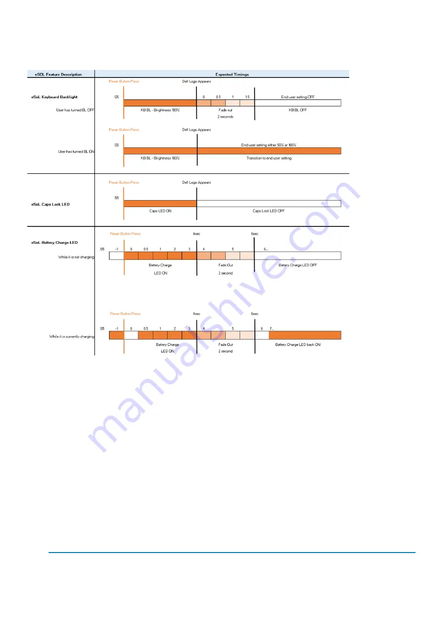
Full boot: Within 22 secs after pressing the power button.
•
Below is the example timelines:
Power button with fingerprint reader will have no LED and will leverage the available LED's in the system to provide indication of the
system status
•
Power Adapter LED:
•
The LED on Power adapter connector illuminates white when power is supplied from electrical outlet.
•
Battery Indicator LED:
•
If the computer is connected to an electrical outlet, the battery light operates as follows:
1. Solid white -the battery is charging. When the charge is complete the LED turns off.
•
If the computer is running on a battery, the battery light operates as follows:
1. Off -the battery is adequately charged (or the computer is turned off).
2. Solid amber -the battery charge is critically low. A low battery state is approximately 30 minutes or less of battery life
remaining.
•
Camera LED
•
White LED activates when camera is on.
•
Mic Mute LED:
•
When activated (muted), the mic mute LED on the F4 Key should illuminate WHITE.
•
RJ45 LEDs:
•
Table 2. LED on either side of RJ45 port
Link connection indicator (LHS)
Activity indicator (RHS)
Green
Amber
Technology and components
13
Содержание Latitude 5310
Страница 1: ...Dell Latitude 5310 Service Manual Regulatory Model P97G Regulatory Type P97G002 ...
Страница 23: ...3 Press the edges and sides of the base cover until it snaps into place Disassembly and reassembly 23 ...
Страница 24: ...4 Tighten the eight captive screws to secure the base cover to the computer 24 Disassembly and reassembly ...
Страница 42: ...2 Route the speaker cable through the routing guides 42 Disassembly and reassembly ...
Страница 46: ...3 Connect the system fan cable to the connector on the system board 46 Disassembly and reassembly ...
Страница 59: ...3 Connect the touchpad button board cable to the connector on the touchpad board Disassembly and reassembly 59 ...
Страница 63: ...9 Release the coin cell battery from the palmrest Disassembly and reassembly 63 ...
Страница 66: ...3 Place the coin cell battery into its slot on the plamrest 66 Disassembly and reassembly ...
Страница 76: ...3 Seat the system chassis on the display assembly 76 Disassembly and reassembly ...
Страница 83: ...4 Adhere the adhesive tape securing the keyboard and the smartcard board Disassembly and reassembly 83 ...
Страница 89: ...3 Reroute the smart card reader cable Disassembly and reassembly 89 ...
Страница 93: ...Disassembly and reassembly 93 ...
Страница 100: ...100 Disassembly and reassembly ...


