background image

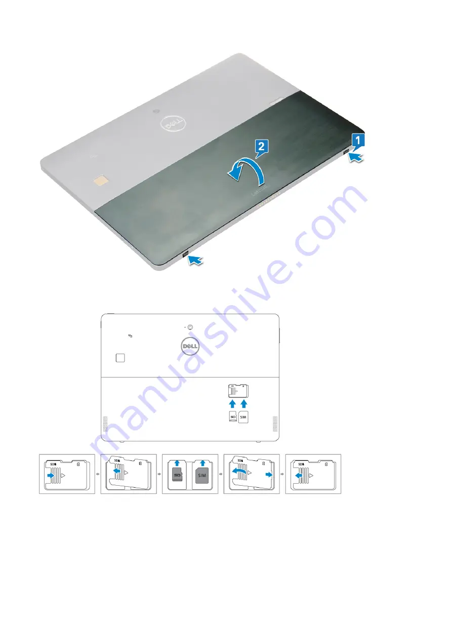
4. Slide the kickstand to an angle 135°, to microSD and micro-SIM cards slot.
5. Insert the SD card and/or micro-SIM cards into the slots indicated on the slots.
6. Align the cover with the groove on the tablet and slide it inside to secure the microSD and the micro-SIM cards.

7. Perform the same steps to remove the microSD / micro-SIM cards

Using your tablet

15

Содержание Latitude 5285

Страница 1: ...Latitude 5285 2 in 1 Owner s Manual Regulatory Model T17G Regulatory Type T17G001 March 2022 Rev A03 ...

Страница 2: ...tial damage to hardware or loss of data and tells you how to avoid the problem WARNING A WARNING indicates a potential for property damage personal injury or death 2016 2022 Dell Inc or its subsidiaries All rights reserved Dell EMC and other trademarks are trademarks of Dell Inc or its subsidiaries Other trademarks may be trademarks of their respective owners ...

Страница 3: ... Inside Your Tablet 13 Turning off your tablet Windows 10 13 After working inside your tablet 14 micro SD micro SIM card 14 Display Panel and display cable 16 Removing the display panel and display cable 16 Installing the display panel 19 Removing the display cable 19 Installing the display cable 20 PCIe Solid State Drive SSD 20 Removing the SSD module 20 Installing SSD module 21 WLAN card 21 Remo...

Страница 4: ... 37 Installing the antenna module 39 USH board 39 Removing the USH board 39 Installing the USH board 40 Chapter 3 Technology and components 42 Power adapter 42 Processors 42 Identifying processors in Windows 10 42 Verifying processor usage in task manager 43 Verifying processor usage in resource monitor 43 Chipset 44 Identifying chipset in device manager on Windows 10 44 Memory features 45 Verifyi...

Страница 5: ...ns 56 Maintenance screen options 56 System logs screen options 57 Updating the BIOS 57 System and setup password 57 Assigning a system password and setup password 58 Deleting or changing an existing system and or setup password 58 Chapter 5 Troubleshooting 59 Enhanced Pre boot System Assessment ePSA 59 Running the ePSA Diagnostic Utility 59 LCD Built in Self Test BIST 59 Method 1 Run the laptop LC...

Страница 6: ...and connector specifications Communication specifications Camera specifications Display specifications AC adapter specifications Battery specifications Physical specifications Environmental specifications Processor specifications Feature Specification Types 7th generation Intel processors System specifications Feature Specification Chipset Integrated in the processor DRAM bus width 64 bit 2 channe...

Страница 7: ...iversal connector Speakers Two Internal speaker amplifier 2 W RMS per channel Volume controls Volume up and Volume down buttons Port and connector specifications Feature Specification Audio Realtek ALC3253 CG Controller Microphone in and stereo headphones speakers universal connector Video Two DisplayPorts over USB Type C Memory card reader micro SD 4 0 Optional smart card reader Micro Subscriber ...

Страница 8: ...a specifications Feature Specification Type Front Camera 5MP fixed focus Rear Camera 8MP auto focus IR Camera VGA IR cameraOptional IR camera Win Hello compliant Sensor type CMOS sensor technology Front and Rear camera Imaging rate Up to 30 frames per second Video Resolution Front Camera 2592 x 1944 pixels Rear Camera 3264 x 2448 pixels Display specifications Feature Specification Type 12 3 3 2 To...

Страница 9: ...perature range Operating 0 C to 40 C 32 F to 104 F Temperature range Non Operating 40 C to 70 C 40 F to 158 F Battery specifications Feature Specification Type 31 5 Whr Polymer battery with ExpressCharge 42 Whr Polymer battery with ExpressCharge 42 WHr Polymer Long Life Cycle 31 5 Whr Length 177 6 mm 6 99 inches Width 82 6 mm 3 25 inches Height 5 5 mm 0 21 inch Weight 135 0 g 0 29 lb 126 GB m2 SAT...

Страница 10: ...mm Height Tablet K eyboard only 0 59 inch 14 9 mm Depth 8 22 inches 208 8 mm Environmental specifications Temperature Specifications Operating 0 C to 35 C 32 F to 95 F Storage 40 C to 65 C 40 F to 149 F Relative humidity maximum Specifications Operating 10 to 90 non condensing Storage 10 to 95 non condensing Altitude maximum Specifications Operating 0 m to 3048 m 0 to 10 000 ft Non operating 0 m t...

Страница 11: ...ay cable PCIe Solid State Drive SSD WLAN card Speaker Battery System fan Heat sink Front facing camera Rear facing camera Smart Card Cage Docking board System Board Coin cell battery Antenna USH board Screw list Table 1 Latitude 5285 2 in 1 Screw size list Component M2 0x 1 1 1 7 M2 0X4 0 M1 6x3 0 M2 0X2 5 M1 6x3 0 M2 0X2 0 M2 0X3 5 Back cover 3 Battery 4 Heat sink 4 Hinges 4 Display panel 6 Syste...

Страница 12: ... 1 rear Antenna module 1 System board 4 Recommended tools The procedures in this document may require the following tools Phillips screwdriver 0 Phillips head screwdriver 1 Phillips head screwdriver Plastic scribe Deploying the kickstand 1 Hold the tablet vertically on a plane surface 2 Press the tablet to allow the kickstand to open 12 Using your tablet ...

Страница 13: ...or on its pull tab not on the cable itself Some cables have connectors with locking tabs if you are disconnecting this type of cable press in on the locking tabs before you disconnect the cable As you pull connectors apart keep them evenly aligned to avoid bending any connector pins Also before you connect a cable ensure that both connectors are correctly oriented and aligned NOTE The color of you...

Страница 14: ...nd any other parts that you removed before working on your tablet 4 Connect your tablet and all attached devices to their electrical outlets 5 Turn on your tablet micro SD micro SIM card uSIM cards can be installed only on tablets shipped with WWAN module 1 Follow the procedure in Before working inside your tablet NOTE disconnect the power and drain flea power before preforming the steps 2 Lay the...

Страница 15: ...Insert the SD card and or micro SIM cards into the slots indicated on the slots 6 Align the cover with the groove on the tablet and slide it inside to secure the microSD and the micro SIM cards 7 Perform the same steps to remove the microSD micro SIM cards Using your tablet 15 ...

Страница 16: ...WAN module 3 Open the kickstand by holding the tablet vertically and pressing it down Place the tablet with the display facing down NOTE You can also open the kickstand from the speaker recess area 4 Place the tablet on a flat surface and lift the stand to reveal the base of the tablet 5 To release the display panel a Remove the M1 6 x 3 0 screws that secure the base cover to the tablet 1 b Close ...

Страница 17: ...6 Use a plastic scribe 1 to pry the edges 2 of the display panel starting from the bottom side first near the docking port NOTE Flip the tablet so the LCD is upward Using your tablet 17 ...

Страница 18: ... panel on a plane surface 8 To disconnect the cables a Disconnect the battery cable on the system board 1 b Disconnect the display cable on the system board 2 9 Lift the display panel from the tablet 18 Using your tablet ...

Страница 19: ...ablet to the display panel 7 Install the a uSIM micro SD card 8 Follow the procedure in After working inside your tablet Removing the display cable 1 Follow the procedure in Before working inside your tablet 2 Remove the a uSIM and or microSD card b display panel 3 Removing the display cable a Peel the tape that secures the touch module cable 1 b Disconnect the touch module cable from the connecto...

Страница 20: ... is installed only on tablets shipping with WWAN module 6 Follow the procedure in After working inside your tablet PCIe Solid State Drive SSD Removing the SSD module 1 Follow the procedure in Before working inside your tablet 2 Remove the a uSIM microSD card NOTE uSIM card slot is available only on tablets shipping with WWAN module b display panel 3 To remove the SSD module a Remove the M2 0 x 2 5...

Страница 21: ...all and delicate Mishandling damages the clips head and needs replacing the shield 3 Replace the M2 0 x 2 5 screw to secure SSD shield NOTE Align the shield carefully to avoid damage to the clips heads 4 Install the a Display panel b uSIM microSD Micro SIM card is installed only on tablets shipped with WWAN module 5 Follow the procedure in after working inside your tablet WLAN card Removing the WL...

Страница 22: ...em board 3 NOTE The system shipped with WiGig model have the optional WiGig orange cable connected Installing the WLAN card 1 Insert the WLAN card into the connector on the system board 2 Connect the antenna cables to the WLAN card 3 Insert the WLAN bracket to the WLAN card 4 Replace the M2 0 x 3 5 screw to secure WLAN bracket 5 Install the a display panel b uSIM microSD NOTE uSIM card is installe...

Страница 23: ...ore space to pry off the speakers b Slide the plastic scribe to clockwise to peel off and remove both speakers from the system chassis c Remove the speaker cable from the connector on the system board Installing speaker 1 Insert the speaker in the block on the system board 2 Connect the cables to the system board 3 Press the speaker to glue it to the adhesive paste on the system 4 Install the a Di...

Страница 24: ...any kind to pry on or against the battery If a battery gets stuck in a device as a result of swelling do not try to free it as puncturing bending or crushing a Lithium ion battery can be dangerous In such an instance the entire system should be replaced Contact https www dell com support for assistance and further instructions Always purchase genuine batteries from https www dell com or authorized...

Страница 25: ...procedure in After working inside your tablet System fan Removing the system fan 1 Follow the procedure in Before working inside your tablet 2 Remove the a uSIM microSD card NOTE Micro SIM card slot is available only on tablets shipped with WWAN module b Display panel 3 To remove the system fan a Disconnect the system fan cable from the system board 1 b Remove the M2 0 x 4 0 screws that secure the...

Страница 26: ...the a display panel NOTE uSIM card is installed only on tablets shipping with WWAN module b uSIM microSD card 5 Follow the procedure in After working inside your tablet Heat sink Removing heat sink assembly 1 Follow the procedure in Before working inside your tablet 2 Remove the a Micro SIM and or microSD card NOTE Micro SIM card slot is available only on tablets shipping with WWAN module b Displa...

Страница 27: ...ly remove the 4 conductive tapes so that the conductive tapes can be reused b Lift the shielding covers that secure the heat sink assembly 2 3 NOTE Peel the black tape copper tape that secure the IR camera cable for model shipped with IR camera optional 4 To remove the heat sink assembly a Loosen the M2 0 x 2 5 captive screws that secure the heat sink assembly to the tablet 1 NOTE Remove the screw...

Страница 28: ...tape copper tape that secure the IR camera cable for model shipped with IR camera optional 4 Affix the conductive tapes to secure the shielding covers 5 Replace the shielding covers to cover the heat sink assembly NOTE The shield covers can break if not handled carefully 6 Install the a display panel b uSIM microSD card NOTE uSIM card is installed only on tablets shipping with WWAN module 7 Follow...

Страница 29: ...e to gently peel off to remove the screw that secures the rear camera to the system board d Remove the M1 6 x 3 0 screws securing the front camera module to the system chassis 4 e Peel off and lift the front camera module from the tablet 5 Installing the front camera 1 Insert the camera module into the slot on the tablet 2 Replace the M1 6 x 3 0 screws to secure the front camera module 3 Connect t...

Страница 30: ...side your tablet 2 Remove the a uSIM microSD NOTE Micro SIM card slot is available only on tablets shipping with WWAN module b Display panel c front facing camera 3 To remove the rear camera a Disconnect the rear camera cable from the system board 1 b Remove the M1 6 x 3 0 screw securing the rear camera module 2 c Lift the camera module from the tablet 3 Installing the rear camera 1 Insert the rea...

Страница 31: ...t Smart Card Cage Removing the smart card cage NOTE Always remove the smart card from the smart card reader 1 Follow the procedure in Before working inside your tablet 2 Remove the a uSIM microSD card NOTE uSIM card slot is available only on tablets shipping with WWAN module b display panel 3 To disconnect the cables a Disconnect the smart card cable from the smart card cage 1 b Remove the M2 0 x ...

Страница 32: ... board 1 Follow the procedure in Before working inside your tablet 2 Remove the a uSIM microSD card NOTE uSIM card slot is available only on tablets shipping with WWAN module b display panel c battery 3 To release the docking board a Disconnect the docking board cable from the system board 1 NOTE The docking board FPC is obstructed by the speaker cable Remove the right speaker first from the syste...

Страница 33: ... module 4 Install the a display panel b uSIM microSD card NOTE uSIM card is installed only on tablets shipping with WWAN module 5 Follow the procedure in After working inside your tablet System Board Removing system board 1 Follow the procedure in Before working inside your tablet 2 Remove the a uSIM microSD card NOTE Micro SIM card slot is available only on tablets shipping with WWAN module b dis...

Страница 34: ...front camera h rear camera i heat sink 3 Disconnect the following cables from the system board a docking board cable 1 b speaker cable 2 c USH board cable 3 4 Un route the antenna cables from the routing clips 1 2 3 4 34 Using your tablet ...

Страница 35: ...5 To remove the system board a Remove the M2 0 x 2 5 screws that secure the system board to the tablet 1 b Lift the system board from the tablet 2 Using your tablet 35 ...

Страница 36: ...m fan e WLAN card NOTE Remove the WWAN card installed on tablets shipped with WWAM module optional f SSD card g battery h display panel i uSIM microSD NOTE uSIM card is installed only on tablets shipping with WWAN module 6 Follow the procedure in After working inside your tablet Coin cell battery Removing the coin cell battery Coin cell battery connector is located beneath the system board 1 Follo...

Страница 37: ...to the connector beneath the system board 3 Install the a battery b display panel c uSIM microSD card NOTE uSIM card is installed only on tablets shipping with WWAN module 4 Follow the procedure in After working inside your tablet Antenna Removing the antenna module 1 Follow the procedure in Before working inside your tablet 2 Remove a uSIM and or microSD card NOTE uSIM card slot is available only...

Страница 38: ...r of the tablet 1 b Un route the cables from routing channels on the back cover 2 c Peel the conductive tape that secures the cables 3 4 To remove the antenna module a Remove the M1 6 x 3 screw that secures the antenna module to the back cover of the tablet 1 b Lift the antenna module from the back cover 2 38 Using your tablet ...

Страница 39: ...conductive tapes to secure the antenna cables 5 Install the a heat sink b rear facing camera c front facing camera d system fan e WLAN card f SSD card g battery h display panel i uSIM microSD card NOTE uSIM card is installed only on tablets shipping with WWAN module 6 Follow the procedure in After working inside your tablet USH board Removing the USH board 1 Follow the procedure in Before working ...

Страница 40: ...e from the connector on the USH board 3 d Remove the M2 0 x 2 5 screw that secures the USH board 4 e Lift the USH board from the tablet 5 Installing the USH board 1 Replace the USB board in the slot on the tablet 2 Connect the M2 0 x 2 5 screw to secure the USH board 3 Connect the USH board cable to the connector on the USH board 4 Connect the NFC and the fingerprint reader cables to the connector...

Страница 41: ...NOTE uSIM card is installed only on tablets shipping with WWAN module 7 Follow the procedure in After working inside your tablet Using your tablet 41 ...

Страница 42: ...ower strips vary among countries Using an incompatible cable or improperly connecting the cable to the power strip or electrical outlet may cause fire or equipment damage Processors Latitude 5285 is shipped with Intel Core i3 7100U Dual Core 3M cache 2 4 GHz 15 W Intel Core i5 7200U Dual Core 3M Cache up to 3 1 GHz 15 W Intel Core i5 7300U vPro Dual Core 3M Cache up to 3 5 GHz 15 W Intel Core i7 7...

Страница 43: ... is displayed 3 Click the Performance tab in the Windows Task Manager window Verifying processor usage in resource monitor 1 Right click the on tablet 2 Select Start Task Manager The Windows Task Manager window is displayed 3 Click the Performance tab in the Windows Task Manager window The processor performance details are displayed 4 Click Open Resource Monitor Technology and components 43 ...

Страница 44: ...anager on Windows 10 NOTE The Chipset information displayed is a generic image and may be different from what is displayed 1 Type Device Manager in the Ask me anything field Device Manager window appears 2 Expand System Devices and search for the chipset 44 Technology and components ...

Страница 45: ...llowing actions after the Dell logo is displayed a With keyboard Press F12 b Press Volume Up button before pressing the Power button to turn on the tablet c Release the Volume Up button once the power sequence is initiated and ePSA will launch The PreBoot System Assessment PSA is launched on your tablet NOTE If you wait too long and the operating system logo appears continue to wait until you see ...

Страница 46: ...evice Manager on Windows 10 1 In the Search box type device manager and tap to start it 2 Under Device Manager expand Imaging devices Starting the camera To start the camera open an application that uses the camera For instance if you tap the Skype software that is shipped with the 2 in 1 the camera turns on Similarly if you are chatting on the internet and the application requests to access the w...

Страница 47: ...t your laptop 2 When the Dell logo appears perform one of the following actions to enter the BIOS setup program With keyboard Tap F2 until the Entering BIOS setup message appears To enter the Boot selection menu tap F12 In tablet mode Press the Volume Up button to display the F12 boot selection or press Volume Down button to enter BIOS setup directly Hard drive is listed under the System Informati...

Страница 48: ...re Magnetic attach feature with built in magnet for increased fastening strength Removed Pen clip and added Tethering functionality Customizable 2 barrel buttons and Top button Quick launch and note taking over lock screen requires Bluetooth pairing LED light to show Bluetooth pairing status 12 months battery life with AAAA battery Based on 3 hours daily usage for 5 days a week 48 Technology and c...

Страница 49: ...navigate follow the procedure Without Keyboard 1 Power on the Latitude tablet 2 Hold down the Volume Down button during startup as the Dell logo appears until the BIOS System Setup page is displayed With Keyboard 1 Power on the Latitude tablet 2 Tap F2 during startup as the Dell logo appears until the BIOS System Setup page is displayed Entering BIOS without keyboard 1 Press the power button to tu...

Страница 50: ...SB Storage Device CD DVD CD RW Drive Onboard NIC Boot sequence options Allows you to change the order in which the tablet attempts to find an operating system Windows boot manager selected by default Boot list options Legacy UEFI selected by default Advanced Boot Options This option allows you the legacy option ROMs to load The options are Enable Legacy Option ROMs default Enable Attempt Legacy Bo...

Страница 51: ...ination levels This field has an effect when the backlight is enabled The options are 5 sec 10 sec enabled by default 15 sec 30 sec 1 min 5 min 15 min Never Keyboard Backlight with AC The Keyboard Backlight with AC option does not affect the main keyboard illumination feature Keyboard Illumination will continue to support the various illumination levels This field has an effect when the backlight ...

Страница 52: ...figuration Allows you to specify the minimum and max password lengths of the Administrator and System passwords min 4 by default if you want to change you can increase the number max 32 you can decrease the number Password Bypass Allows you to enable or disable the permission to bypass the System and the Internal HDD password when they are set The options are Disabled Reboot bypass Default setting...

Страница 53: ...cure Boot screen options Option Description Secure Boot Enable This option enables or disables the Secure Boot feature Disabled Enabled Default setting Enabled Expert Key Management Allows you to manage all secure boot keys Manage All Factory Keys PK KEK DB DBX NOTE For Secure Boot to be enabled the system needs to be in UEFI boot mode and the Enable Legacy Option ROMs option needs to be turned of...

Страница 54: ...HyperThread Control Allows you to enable or disable the Hyper Threading in the processor Disabled Enabled Default setting Enabled is selected Power management screen options Option Description AC Behavior Allows you to enable or disable the tablet from turning on automatically when an AC adapter is connected Default setting Wake on AC is not selected Auto On Time Allows you to set the time at whic...

Страница 55: ...OS warning messages when you use certain power adapters Default setting Enable Adapter Warnings Keypad Embedded Allows you to choose one of two methods to enable the keypad that is embedded in the internal keyboard Fn Key Only enabled by default By Numlock NOTE When setup is running this option has no effect Setup works in Fn Key Only mode Numlock Enable Allows you to enable the Numlock option whe...

Страница 56: ...nal hardware capabilities provided by Intel Trusted Execution Technology The TPM Virtualization Technology and the Virtualization technology for direct I O must be enabled to use this feature Trusted Execution disabled by default Wireless screen options Option Description Wireless Device Enable Allows you to enable or disable the internal wireless devices WWAN GPS WLAN WiGig Bluetooth All the opti...

Страница 57: ...the Service Tag click the Product Category of your tablet 5 Choose the Product Type from the list 6 Select your tablet model and the Product Support page of your tablet appears 7 Click Get drivers and click View All Drivers The Drivers and Downloads page opens 8 On the Drivers and Downloads screen under the Operating System drop down list select BIOS 9 Identify the latest BIOS file and click Downl...

Страница 58: ...d that you entered earlier in the Confirm new password field and click OK 4 Press Esc and a message prompts you to save the changes 5 Press Y to save the changes The computer reboots Deleting or changing an existing system and or setup password Ensure that the Password Status is Unlocked in the System Setup before attempting to delete or change the existing System and or Setup password You cannot ...

Страница 59: ...NOTE The following steps can be used to run the ePSA diagnostic utility in DOS mode without using an external keyboard 1 Power on the system 2 Before the Dell Logo is displayed immediately press the Volume Up button to get the Boot Menu 3 Scroll down the Diagnostics and then press the Volume Down button to select 4 The tablet will begin running the ePSA utility LCD Built in Self Test BIST Dell lap...

Страница 60: ...en you see the message Do you see the color bars Yes No NOTE If you do not respond for 30 seconds the diagnostics will automatically assume your response as No and proceed to the laptop LCD built in self test BIST 7 The screen will display multiple color bars and change colors on the entire screen to black white red green and blue 8 Carefully inspect the screen for abnormalities 9 The PC will rest...

Страница 61: ...failure 2 2 system board BIOS ROM system board covers BIOS corruption or ROM error 2 3 memory no memory no RAM detected 2 4 memory memory failure RAM failure 2 5 memory invalid memory installed 2 6 system board chipset system board chipset error 2 7 display display failure 3 1 RTC power failure coin cell battery failure 3 2 PCI Video PCI Video card chip failure 3 3 BIOS recovery 1 recovery image n...

Страница 62: ...AC adapter shipped with your tablet AC adapters are shipped based on customer requirements or based on regions To identify the AC adapter shipped with your tablet you can verify it from the service tag 1 Go to Dell com support 2 Type the service tag of your tablet 3 Click System configuration System configuration details are displayed 4 Click Original configuration to view the AC adapter shipped w...

Страница 63: ... service options Availability varies by country and product and some services may not be available in your area To contact Dell for sales technical support or customer service issues 1 Go to Dell com support 2 Select your support category 3 Verify your country or region in the Choose a Country Region drop down list at the bottom of the page 4 Select the appropriate service or support link based on...

Отзывы: