Dell Inspiron 5557 Скачать руководство пользователя страница 32

Peel the I/O-board cable off the fan.

1

latch

2

I/O-board cable

3

fan

Disconnect the display-cable from the system board.

32

Содержание Inspiron 5557

Страница 1: ...Inspiron 15 5000 Series Service Manual Computer Model Inspiron 15 5557 Regulatory Model P39F Regulatory Type P39F003 ...

Страница 2: ...problem WARNING A WARNING indicates a potential for property damage personal injury or death Copyright 2015 Dell Inc All rights reserved This product is protected by U S and international copyright and intellectual property laws Dell and the Dell logo are trademarks of Dell Inc in the United States and or other jurisdictions All other marks and names mentioned herein may be trademarks of their res...

Страница 3: ...ide your computer 13 Removing the base cover 14 Procedure 14 Replacing the base cover 16 Procedure 16 Removing the battery 17 Prerequisites 17 Procedure 17 Replacing the battery 18 Procedure 18 Post requisites 18 Removing the hard drive 19 Prerequisites 19 Procedure 19 Replacing the hard drive 22 Procedure 22 Post requisites 22 3 ...

Страница 4: ...card 27 Prerequisites 27 Procedure 27 Replacing the wireless card 29 Procedure 29 Post requisites 30 Removing the fan 31 Prerequisites 31 Procedure 31 Replacing the fan 35 Procedure 35 Post requisites 35 Removing the keyboard 36 Prerequisites 36 Procedure 36 Replacing the keyboard 39 Procedure 39 Folding the keyboard cables 39 Post requisites 41 4 ...

Страница 5: ... battery 49 Prerequisites 49 Procedure 50 Replacing the coin cell battery 51 Procedure 51 Post requisites 51 Removing the heat sink 52 Prerequisites 52 Procedure 52 Replacing the heat sink 54 Procedure 54 Post requisites 54 Removing the I O board 55 Prerequisites 55 Procedure 55 Replacing the I O board 57 Procedure 57 Post requisites 57 5 ...

Страница 6: ...uisites 61 Procedure 61 Replacing the status light board 64 Procedure 64 Post requisites 64 Removing the display assembly 65 Prerequisites 65 Procedure 65 Replacing the display assembly 67 Procedure 67 Post requisites 67 Removing the power adapter port 68 Prerequisites 68 Procedure 68 Replacing the power adapter port 70 Procedure 70 Post requisites 70 6 ...

Страница 7: ...ram 76 Removing the palm rest 77 Prerequisites 77 Procedure 78 Replacing the palm rest 80 Procedure 80 Post requisites 80 Removing the display bezel 81 Prerequisites 81 Procedure 81 Replacing the display bezel 83 Procedure 83 Post requisites 83 Removing the display panel 84 Prerequisites 84 Procedure 84 Replacing the display panel 86 Procedure 86 Post requisites 86 7 ...

Страница 8: ...ites 90 Procedure 90 Replacing the display hinges 92 Procedure 92 Post requisites 92 Removing the camera 93 Prerequisites 93 Procedure 93 Replacing the camera 95 Procedure 95 Post requisites 95 Removing the display back cover and antenna assembly 96 Prerequisites 96 Procedure 96 Replacing the display back cover and antenna assembly 98 Procedure 98 Post requisites 98 8 ...

Страница 9: ...Flashing the BIOS 99 Getting help and contacting Dell 100 Self help resources 100 Contacting Dell 101 9 ...

Страница 10: ...Shut down Windows 7 Click or tap Start Shut down NOTE If you are using a different operating system see the documentation of your operating system for shut down instructions 3 Disconnect your computer and all attached devices from their electrical outlets 4 Disconnect all cables such as telephone cables network cables and so on from your computer 5 Disconnect all attached devices and peripherals s...

Страница 11: ...l is not covered by your warranty See the safety instructions that shipped with the product or at www dell com regulatory_compliance CAUTION Before touching anything inside your computer ground yourself by touching an unpainted metal surface such as the metal at the back of the computer While you work periodically touch an unpainted metal surface to dissipate static electricity which could harm in...

Страница 12: ... Plastic scribe 12 ...

Страница 13: ...sure that no stray screws remain inside your computer 2 Connect any external devices peripherals and cables you removed before working on your computer 3 Replace any media cards discs and any other parts that you removed before working on your computer 4 Connect your computer and all attached devices to their electrical outlets 5 Turn on your computer 13 ...

Страница 14: ...r computer After working inside your computer follow the instructions in After working inside your computer For more safety best practices see the Regulatory Compliance home page at www dell com regulatory_compliance Procedure 1 Close the display and turn the computer over 2 Remove the screws that secure the base cover to the base frame 1 screws 2 2 base cover 3 base frame 14 ...

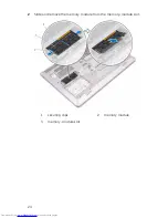
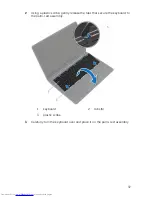
Страница 15: ...3 Using a plastic scribe pry the base cover off the base frame 1 plastic scribe 2 notch 3 base cover 15 ...

Страница 16: ...omputer After working inside your computer follow the instructions in After working inside your computer For more safety best practices see the Regulatory Compliance home page at www dell com regulatory_compliance Procedure 1 Slide the tabs on the base cover into the base frame and snap the base cover into place 2 Replace the screws that secure the base cover to the base frame 16 ...

Страница 17: ...ing inside your computer For more safety best practices see the Regulatory Compliance home page at www dell com regulatory_compliance Prerequisites Remove the base cover Procedure 1 Remove the screws that secure the battery to the base frame 2 Using the pull tab slide and lift the battery off the base frame 1 pull tab 2 screws 4 3 battery 3 Turn the computer over open the display and press the pow...

Страница 18: ...low the instructions in After working inside your computer For more safety best practices see the Regulatory Compliance home page at www dell com regulatory_compliance Procedure 1 Align the screw holes on the battery with the screw holes on the base frame and press down the battery to connect it to the battery connector 2 Replace the screws that secure the battery to the base frame Post requisites...

Страница 19: ...working inside your computer For more safety best practices see the Regulatory Compliance home page at www dell com regulatory_compliance CAUTION Hard drives are fragile Exercise care when handling the hard drive CAUTION To avoid data loss do not remove the hard drive while the computer is in sleep or on state Prerequisites 1 Remove the base cover 2 Remove the battery Procedure 1 Remove the screws...

Страница 20: ...ssembly out of the base frame 1 pull tab 2 screws 4 3 hard drive assembly 3 Disconnect the hard drive cable from the hard drive 1 hard drive assembly 2 hard drive cable 4 Remove the screws that secure the hard drive bracket to the hard drive 20 ...

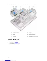
Страница 21: ...5 Lift the hard drive off the hard drive bracket 1 hard drive 2 screws 4 3 hard drive bracket 21 ...

Страница 22: ... drives are fragile Exercise care when handling the hard drive Procedure 1 Place the hard drive in the hard drive bracket and align the screw holes on the hard drive bracket with the screw holes on the hard drive 2 Replace the screws that secure the hard drive bracket to the hard drive 3 Connect the hard drive cable to the hard drive 4 Slide the hard drive in the base frame and align the screw hol...

Страница 23: ...er working inside your computer follow the instructions in After working inside your computer For more safety best practices see the Regulatory Compliance home page at www dell com regulatory_compliance Prerequisites 1 Remove the base cover 2 Remove the battery Procedure 1 Using your fingertips pry apart the securing clips on each end of the memory module slot until the memory module pops up 23 ...

Страница 24: ...2 Slide and remove the memory module from the memory module slot 1 securing clips 2 memory module 3 memory module slot 24 ...

Страница 25: ...the steps in Before working inside your computer After working inside your computer follow the instructions in After working inside your computer For more safety best practices see the Regulatory Compliance home page at www dell com regulatory_compliance Procedure 1 Align the notch on the memory module with the tab on the memory module slot 25 ...

Страница 26: ...ss the memory module down until it clicks into place NOTE If you do not hear the click remove the memory module and reinstall it 1 securing clips 2 2 memory module slot 3 tab 4 notch 5 memory modules 2 Post requisites 1 Replace the battery 2 Replace the base cover 26 ...

Страница 27: ...ollow the instructions in After working inside your computer For more safety best practices see the Regulatory Compliance home page at www dell com regulatory_compliance Prerequisites 1 Remove the base cover 2 Remove the battery Procedure 1 Remove the screw that secures the wireless card bracket to the system board 2 Lift the wireless card bracket off the wireless card 3 Disconnect the antenna cab...

Страница 28: ...4 Lift and slide the wireless card out of the wireless card slot 1 screw 2 wireless card bracket 3 antenna cables 4 wireless card 5 wireless card slot 28 ...

Страница 29: ...oid damaging the wireless card do not place any cables under it 1 Align the notches on the wireless card with the tabs on the wireless card slot 2 Slide the wireless card at an angle into the wireless card slot 3 Connect the antenna cables to the wireless card The following table provides the antenna cable color scheme for the wireless card supported by your computer Connectors on the wireless car...

Страница 30: ...he screw that secures the wireless card bracket to the system board 1 wireless card 2 notch 3 tab 4 antenna cables 5 screw 6 wireless card bracket Post requisites 1 Replace the battery 2 Replace the base cover 30 ...

Страница 31: ...e your computer After working inside your computer follow the instructions in After working inside your computer For more safety best practices see the Regulatory Compliance home page at www dell com regulatory_compliance Prerequisites 1 Remove the base cover 2 Remove the battery Procedure 1 Lift the latch and disconnect the I O board cable from the system board 31 ...

Страница 32: ...2 Peel the I O board cable off the fan 1 latch 2 I O board cable 3 fan 3 Disconnect the display cable from the system board 32 ...

Страница 33: ...e cable from the routing guides 1 routing guide 2 display cable 5 Disconnect the fan cable from the system board 6 Note the fan cable routing and remove the cable from the routing guides 7 Remove the screws that secure the fan to the base frame 33 ...

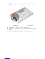
Страница 34: ...8 Lift the fan off the base frame 1 screws 2 2 fan 3 fan cable 34 ...

Страница 35: ...e Procedure 1 Align the screw holes on the fan with the screw holes on the base frame 2 Replace the screws that secure the fan to the base frame 3 Route the fan cable through the routing guides on the base frame 4 Connect the fan cable to the system board 5 Route the display cable through the routing guides on the base frame 6 Connect the display cable to the system board 7 Adhere the I O board ca...

Страница 36: ...g inside your computer After working inside your computer follow the instructions in After working inside your computer For more safety best practices see the Regulatory Compliance home page at www dell com regulatory_compliance Prerequisites 1 Remove the base cover 2 Remove the battery Procedure 1 Turn the computer over and open the display as far as possible 36 ...

Страница 37: ...g a plastic scribe gently release the tabs that secure the keyboard to the palm rest assembly 1 keyboard 2 tabs 6 3 plastic scribe 3 Carefully turn the keyboard over and place it on the palm rest assembly 37 ...

Страница 38: ...backlight cables from the system board NOTE The keyboard backlight cable is present only if the laptop is shipped with a backlit keyboard 1 keyboard cable 2 latch 3 keyboard backlight cable 5 Lift the keyboard along with the cables off the palm rest assembly 38 ...

Страница 39: ...s the same way they are folded on the old keyboard For more information see Folding the keyboard cables 1 Slide the keyboard and keyboard backlight cables into the respective connectors and press down the latches to secure the cables 2 Turn the keyboard over slide the tabs on the keyboard into the slots on the palm rest assembly and snap the keyboard into place Folding the keyboard cables CAUTION ...

Страница 40: ...on a flat and clean surface 1 keyboard cable 2 keyboard backlight cable 3 keyboard CAUTION Do not apply excess pressure while folding the cables 2 Lift the keyboard cable and gently fold the keyboard backlight cable at the fold line 1 keyboard cable 2 keyboard backlight cable 3 fold line 40 ...

Страница 41: ...3 Using the alignment line gently fold the keyboard cable 1 keyboard cable 2 alignment line Post requisites 1 Replace the battery 41 ...

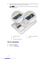
Страница 42: ...2 Replace the base cover 42 ...

Страница 43: ...puter After working inside your computer follow the instructions in After working inside your computer For more safety best practices see the Regulatory Compliance home page at www dell com regulatory_compliance Prerequisites 1 Remove the base cover 2 Remove the battery 3 Follow the procedure from step 1 to step 3 in removing the hard drive 4 Remove the fan 5 Remove the keyboard 43 ...

Страница 44: ...Procedure 1 Lift the latch and disconnect the touch pad cable from the system board 1 latch 2 touch pad cable 3 palm rest assembly 44 ...

Страница 45: ...2 Remove the screws that secure the base frame to the palm rest assembly 1 screws 10 2 palm rest assembly 3 Close the display and turn the computer over 45 ...

Страница 46: ...4 Remove the screws that secure the base frame to the palm rest assembly 1 screws 9 2 base frame 46 ...

Страница 47: ...Using your fingertips starting from the rear pry the base frame off the palm rest assembly NOTE Make sure the display cable is completely removed from the routing guides on the base frame 1 base frame 47 ...

Страница 48: ...ocedure 1 Align the tabs on the base frame with the slots on the palm rest assembly and snap the base frame into place 2 Replace the screws that secure the base frame to the palm rest assembly 3 Turn the computer over and open the display 4 Replace the screws that secure the base frame to the palm rest assembly 5 Slide the touch pad cable into the connector on the system board and close the latch ...

Страница 49: ... more safety best practices see the Regulatory Compliance home page at www dell com regulatory_compliance CAUTION Removing the coin cell battery resets the BIOS setup program s settings to default It is recommended that you note the BIOS setup program s settings before removing the coin cell battery Prerequisites 1 Remove the base cover 2 Remove the battery 3 Follow the procedure from step 1 to st...

Страница 50: ...the coin cell battery cable from the system board 1 coin cell battery 2 coin cell battery cable 2 Peel off the coin cell battery from the system board 3 Lift the coin cell battery along with its cable off the system board 50 ...

Страница 51: ...r working inside your computer For more safety best practices see the Regulatory Compliance home page at www dell com regulatory_compliance Procedure 1 Adhere the coin cell battery to the system board 2 Connect the coin cell battery cable to the system board Post requisites 1 Replace the base frame 2 Replace the keyboard 3 Replace the fan 4 Follow the procedure from step 3 to step 5 in replacing t...

Страница 52: ...k may become hot during normal operation Allow sufficient time for the heat sink to cool before you touch it CAUTION For maximum cooling of the processor do not touch the heat transfer areas on the heat sink The oils in your skin can reduce the heat transfer capability of the thermal grease Prerequisites 1 Remove the base cover 2 Remove the battery 3 Follow the procedure from step 1 to step 3 in r...

Страница 53: ...tem board 1 screws 6 2 processor heat sink 3 graphics card heat sink NOTE The image shows a heat sink on a laptop shipped with discrete graphics card The heat sink shipped on a laptop with integrated graphics card has only 4 screws 53 ...

Страница 54: ...either the system board or the heat sink is replaced use the thermal pad provided in the kit to ensure that thermal conductivity is achieved Procedure NOTE The original thermal grease can be reused if the original system board and fan are reinstalled together If either the system board or the fan is replaced use the thermal pad provided in the kit to make sure that thermal conductivity is achieved...

Страница 55: ...structions in After working inside your computer For more safety best practices see the Regulatory Compliance home page at www dell com regulatory_compliance Prerequisites 1 Remove the base cover 2 Remove the battery 3 Follow the procedure from step 1 to step 3 in removing the hard drive 4 Remove the fan 5 Remove the keyboard 6 Remove the base frame Procedure 1 Remove the screw that secures the I ...

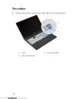
Страница 56: ...2 Lift the I O board off the palm rest assembly 1 screw 2 I O board 56 ...

Страница 57: ...r For more safety best practices see the Regulatory Compliance home page at www dell com regulatory_compliance Procedure 1 Align the screw hole on the I O board with the screw hole on the palm rest assembly 2 Replace the screw that secures the I O board to the palm rest assembly Post requisites 1 Replace the base frame 2 Replace the keyboard 3 Replace the fan 4 Follow the procedure from step 3 to ...

Страница 58: ...puter For more safety best practices see the Regulatory Compliance home page at www dell com regulatory_compliance Prerequisites 1 Remove the base cover 2 Remove the battery 3 Follow the procedure from step 1 to step 3 in removing the hard drive 4 Remove the fan 5 Remove the keyboard 6 Remove the base frame Procedure 1 Disconnect the speaker cable from the system board 2 Note the speaker cable rou...

Страница 59: ...3 Lift the speakers along with the speaker cable off the palm rest assembly 1 speaker cable 2 speakers 2 59 ...

Страница 60: ...ty best practices see the Regulatory Compliance home page at www dell com regulatory_compliance Procedure 1 Align the speakers to the alignment posts on the palm rest 2 Route the speaker cable through the routing guides on the palm rest assembly 3 Connect the speaker cable to the system board Post requisites 1 Replace the base frame 2 Replace the keyboard 3 Replace the fan 4 Follow the procedure f...

Страница 61: ...uter follow the instructions in After working inside your computer For more safety best practices see the Regulatory Compliance home page at www dell com regulatory_compliance Prerequisites 1 Remove the base cover 2 Remove the battery 3 Follow the procedure from step 1 to step 3 in removing the hard drive 4 Remove the fan 5 Remove the keyboard 6 Remove the base frame Procedure 1 Turn over the comp...

Страница 62: ...rom the system board 1 latch 2 status light board cable 3 palm rest assembly 3 Close the display and turn the computer over 4 Remove the screw that secures the status light board to the palm rest 5 Peel off the status light board cable from the palm rest 62 ...

Страница 63: ...6 Lift the status light board along with the cable off the palm rest 1 screw 2 status light board 3 status light board cable 4 palm rest 63 ...

Страница 64: ...Procedure 1 Align the screw hole on the status light board with the screw hole on the palm rest 2 Replace the screw that secures the status light board to the palm rest 3 Adhere the status light board cable to the palm rest 4 Slide the status light board cable through the slot on the palm rest 5 Turn the computer over and open the display 6 Connect the status light board cable to the system board ...

Страница 65: ...gulatory Compliance home page at www dell com regulatory_compliance Prerequisites 1 Remove the base cover 2 Remove the battery 3 Follow the procedure from step 1 to step 3 in removing the hard drive 4 Remove the wireless card 5 Remove the fan 6 Remove the keyboard 7 Remove the base frame Procedure 1 Place the computer on a flat table and open the display at a right angle as shown 2 Peel off the ta...

Страница 66: ...4 Lift the display assembly off the palm rest assembly 1 antenna cables 2 system board 3 tape 4 screws 3 5 display assembly 66 ...

Страница 67: ...ww dell com regulatory_compliance Procedure 1 Place the computer on a flat table and align the screw holes on the palm rest assembly with the screw holes on the display hinges 2 Press down the display hinges and replace the screws that secure the display hinges to the palm rest assembly 3 Adhere the antenna cables to the system board Post requisites 1 Replace the base frame 2 Replace the keyboard ...

Страница 68: ... more safety best practices see the Regulatory Compliance home page at www dell com regulatory_compliance Prerequisites 1 Remove the base cover 2 Remove the battery 3 Follow the procedure from step 1 to step 3 in removing the hard drive 4 Remove the fan 5 Remove the keyboard 6 Remove the base frame 7 Remove the heat sink 8 Remove the display assembly Procedure 1 Peel off the power adapter port cab...

Страница 69: ...3 Pry the power adapter port out of the slot on the palm rest 1 power adapter port cable 2 power adapter port 69 ...

Страница 70: ... Regulatory Compliance home page at www dell com regulatory_compliance Procedure 1 Slide the power adapter port into the slot in the palm rest assembly 2 Connect the power adapter port cable to the system board 3 Adhere the power adapter port cable to the palm rest assembly Post requisites 1 Replace the display assembly 2 Replace the heat sink 3 Replace the base frame 4 Replace the keyboard 5 Repl...

Страница 71: ...cing the system board removes any changes you have made to the BIOS using the BIOS setup program You must make the desired changes again after you replace the system board NOTE Before disconnecting the cables from the system board note the location of the connectors so that you can reconnect the cables correctly after you replace the system board Prerequisites 1 Remove the base cover 2 Remove the ...

Страница 72: ...er port cable 2 antenna cable 3 speaker cable 4 hard drive cable 3 Remove the screws that secure the system board to the palm rest assembly 4 Starting from the inner edge gently lift the system board and release the ports from the slots on the palm rest assembly 72 ...

Страница 73: ...5 Lift the system board off the palm rest assembly 1 screws 2 2 system board 73 ...

Страница 74: ...rvice Tag is stored in the system board You must enter the Service Tag in the BIOS setup program after you replace the system board NOTE Replacing the system board removes any changes you have made to the BIOS using the BIOS setup program You must make the desired changes again after you replace the system board Procedure CAUTION Make sure that no cables are placed under the system board 1 Slide t...

Страница 75: ...hip 1 antenna cable 2 chip 3 palm rest 4 Connect the hard drive cable speaker cable and power adapter port to the system board Post requisites 1 Replace the heat sink 2 Replace the display assembly 3 Replace the base frame 4 Replace the keyboard 5 Replace the fan 6 Replace the wireless card 7 Replace the memory modules 8 Follow the procedure from step 3 to step 5 in replacing the hard drive 9 Repl...

Страница 76: ...ring the Service Tag in the BIOS setup program 1 Turn on the computer 2 Press F2 when the DELL logo is displayed to enter the BIOS setup program 3 Navigate to the Main tab and enter the Service Tag in the Service Tag Input field 76 ...

Страница 77: ...omputer For more safety best practices see the Regulatory Compliance home page at www dell com regulatory_compliance Prerequisites 1 Remove the base cover 2 Remove the battery 3 Follow the procedure form step 1 to step 3 in removing the hard drive 4 Remove the fan 5 Remove the keyboard 6 Remove the base frame 7 Remove the heat sink 8 Remove the I O board 9 Remove the speakers 10 Remove the display...

Страница 78: ...Procedure 1 Remove the screws that secure the system board to the palm rest 1 screws 2 2 system board 78 ...

Страница 79: ...2 Lift the system board from the inner edge and release the ports from the slots on the palm rest 1 screws 2 2 system board 1 palm rest 79 ...

Страница 80: ...re 1 Slide the headset port into the slot on the palm rest and align the screw holes on the system board with the screw holes on the palm rest assembly 2 Replace the screws that secure the system board to the palm rest assembly Post requisites 1 Replace the status light board 2 Replace the power adapter port 3 Replace the display assembly 4 Replace the speakers 5 Replace the I O board 6 Replace th...

Страница 81: ...safety best practices see the Regulatory Compliance home page at www dell com regulatory_compliance Prerequisites NOTE These instructions are applicable only for laptops with a non touchscreen display 1 Remove the base cover 2 Remove the battery 3 Follow the procedure from step 1 to step 3 in removing the hard drive 4 Remove the fan 5 Remove the keyboard 6 Remove the base frame 7 Remove the displa...

Страница 82: ...2 Lift the display bezel off the display assembly 1 display bezel 82 ...

Страница 83: ...nside your computer For more safety best practices see the Regulatory Compliance home page at www dell com regulatory_compliance Procedure Align the display bezel with the display back cover and gently snap the display bezel into place Post requisites 1 Replace the display assembly 2 Replace the keyboard 3 Replace the base frame 4 Replace the fan 5 Follow the procedure from step 3 to step 5 in rep...

Страница 84: ...actices see the Regulatory Compliance home page at www dell com regulatory_compliance Prerequisites NOTE These instructions are applicable only for laptops with a non touchscreen display 1 Remove the base cover 2 Remove the battery 3 Follow the procedure from step 1 to step 3 in removing the hard drive 4 Remove the fan 5 Remove the keyboard 6 Remove the base frame 7 Remove the display assembly 8 R...

Страница 85: ...t the display panel slightly off the display back cover rotate it and place it face down on a clean surface 1 screws 4 2 display panel 3 Disconnect the display cable from the display panel 1 display cable 85 ...

Страница 86: ... com regulatory_compliance Procedure 1 Connect the display cable to the display panel 2 Place the display panel on the display back cover and align the screw holes on the display panel with the screw holes on the display back cover 3 Replace the screws that secure the display panel to the display back cover Post requisites 1 Replace the display bezel 2 Replace the display assembly 3 Replace the ba...

Страница 87: ...actices see the Regulatory Compliance home page at www dell com regulatory_compliance Prerequisites NOTE These instructions are applicable only for laptops with a non touchscreen display 1 Remove the base cover 2 Remove the battery 3 Follow the procedure from step 1 to step 3 in removing the hard drive 4 Remove the fan 5 Remove the keyboard 6 Remove the base frame 7 Remove the display assembly 8 R...

Страница 88: ...2 Lift the display brackets off the display back cover 1 screws 10 2 display back cover 3 display brackets 2 88 ...

Страница 89: ...me page at www dell com regulatory_compliance Procedure 1 Slide the brackets under the tabs on the display back cover 2 Align the screw holes on the display brackets with the screw holes on the display back cover 3 Replace the screws that secure the display brackets to the display back cover Post requisites 1 Replace the display bezel 2 Replace the display assembly 3 Replace the base frame 4 Repla...

Страница 90: ...mpliance home page at www dell com regulatory_compliance Prerequisites NOTE These instructions are applicable only for laptops with a non touchscreen display 1 Remove the base cover 2 Remove the battery 3 Follow the procedure from step 1 to step 3 in removing the hard drive 4 Remove the fan 5 Remove the keyboard 6 Remove the base frame 7 Remove the display assembly 8 Remove the display bezel 9 Rem...

Страница 91: ...2 Lift the display hinges off the display back cover 1 screws 4 2 display hinges 2 3 display back cover 91 ...

Страница 92: ...home page at www dell com regulatory_compliance Procedure 1 Align the screw holes on the display hinges with the screw holes on the display back cover 2 Replace the screws that secure the display hinges to the display back cover Post requisites 1 Replace the display brackets 2 Replace the display panel 3 Replace the display bezel 4 Replace the display assembly 5 Replace the base frame 6 Replace th...

Страница 93: ...tices see the Regulatory Compliance home page at www dell com regulatory_compliance Prerequisites NOTE These instructions are applicable only for laptops with a non touchscreen display 1 Remove the base cover 2 Remove the battery 3 Follow the procedure from step 1 to step 3 in removing the hard drive 4 Remove the fan 5 Remove the keyboard 6 Remove the base frame 7 Remove the display assembly 8 Rem...

Страница 94: ...2 Disconnect the camera cable from the camera 1 camera cable 2 camera 3 plastic scribe 94 ...

Страница 95: ...mputer For more safety best practices see the Regulatory Compliance home page at www dell com regulatory_compliance Procedure 1 Connect the camera cable to the camera 2 Adhere the camera to the display back cover Post requisites 1 Replace the display bezel 2 Replace the display assembly 3 Replace the base frame 4 Replace the keyboard 5 Replace the fan 6 Follow the procedure from step 3 to step 5 i...

Страница 96: ...at www dell com regulatory_compliance Prerequisites NOTE These instruction are applicable only to laptops with a non touchscreen display 1 Remove the base cover 2 Remove the battery 3 Follow the procedure from step 1 to step 3 in removing the hard drive 4 Remove the fan 5 Remove the keyboard 6 Remove the base frame 7 Remove the display assembly 8 Remove the display bezel 9 Remove the display panel...

Страница 97: ...1 camera cable 2 display cable 97 ...

Страница 98: ...he Regulatory Compliance home page at www dell com regulatory_compliance Procedure Route the display cable and camera cable through the routing guides on the display back cover Post requisites 1 Replace the camera 2 Replace the display hinges 3 Replace the display brackets 4 Replace the display panel 5 Replace the display bezel 6 Replace the display assembly 7 Replace the base frame 8 Replace the ...

Страница 99: ...have the Service Tag use the auto detect feature or manually browse for your computer model 4 Click Drivers downloads 5 Select the operating system installed on your computer 6 Scroll down the page and expand BIOS 7 Click Download File to download the latest version of the BIOS for your computer 8 Save the file and once the download is complete navigate to the folder where you saved the BIOS updat...

Страница 100: ...ows 8 1 and Windows 10 In Windows search type Help and Support and press Enter Accessing help in Windows 7 Click Start Help and Support Online help for operating system www dell com support windows www dell com support linux Troubleshooting information user manuals setup instructions product specifications technical help blogs drivers software updates and so on www dell com support Learn about you...

Страница 101: ...see www dell com contactdell NOTE Availability varies by country and product and some services may not be available in your country NOTE If you do not have an active internet connection you can find contact information on your purchase invoice packing slip bill or Dell product catalog 101 ...

Отзывы: