background image

Installing the M.2 2230 solid-state drive

Prerequisites

If you are replacing a component, remove the existing component before performing the installation procedure.

About this task

NOTE:

 This procedure applies if you are installing a M.2 2230 solid-state drive.

NOTE:

 The M.2 card that is installed on your computer will depend on the configuration ordered. Supported card

configurations on the M.2 card slot:

M.2 2230 solid-state drive + 2230 mounting bracket

M.2 2280 solid-state drive

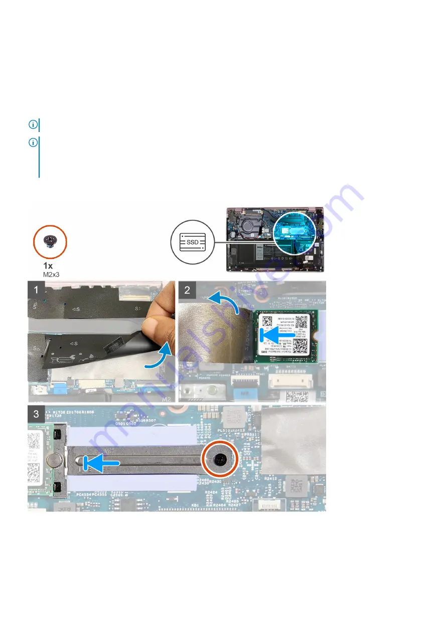
The following images indicate the location of the M.2 2230 solid-state drive and provide a visual representation of the
installation procedure.

Steps

1. Lift the Mylar that covers the system board.
2. Lift the thermal tape over the M.2 2230 solid-state drive and bracket.
3. Align the notch on the M.2 2230 solid-state drive with the tab on the M.2 card slot on the system board.
4. Slide the M.2 2230 solid-state drive into the M.2 card slot on the system board.

Removing and installing components

21

Содержание Inspiron 5301

Страница 1: ...Inspiron 5301 Service Manual Regulatory Model P121G Regulatory Type P121G002 August 2021 Rev A01 ...

Страница 2: ...tial damage to hardware or loss of data and tells you how to avoid the problem WARNING A WARNING indicates a potential for property damage personal injury or death 2020 2021 Dell Inc or its subsidiaries All rights reserved Dell EMC and other trademarks are trademarks of Dell Inc or its subsidiaries Other trademarks may be trademarks of their respective owners ...

Страница 3: ...Removing the M 2 2230 solid state drive 19 Installing the M 2 2230 solid state drive 21 Removing the M 2 2280 solid state drive 22 Installing the M 2 2280 solid state drive 23 Coin cell battery 25 Removing the coin cell battery 25 Installing the coin cell battery 25 Fans 26 Removing the fan 26 Installing the fan 27 Speakers 28 Removing the speakers 28 Installing the speakers 29 Display assembly 30...

Страница 4: ... 55 System setup options 56 System and setup password 62 Assigning a system setup password 63 Deleting or changing an existing system or admin password 63 Clearing CMOS settings 63 Clearing BIOS System Setup and System passwords 64 Updating the BIOS 64 Updating the BIOS in Windows 64 Updating the BIOS using the USB drive in Windows 64 Updating the BIOS in Linux and Ubuntu 65 Updating the BIOS from...

Страница 5: ...ot covered by your warranty See the safety instructions that is shipped with the product or at www dell com regulatory_compliance CAUTION Before touching anything inside your computer ground yourself by touching an unpainted metal surface such as the metal at the back of the computer While you work periodically touch an unpainted metal surface to dissipate static electricity which could harm inter...

Страница 6: ...lures means that most of the time when damage occurs it is not immediately recognizable The DIMM receives a static shock but the tracing is merely weakened and does not immediately produce outward symptoms related to the damage The weakened trace may take weeks or months to melt and in the meantime may cause degradation of memory integrity intermittent memory errors etc The more difficult type of ...

Страница 7: ...kspace should also be free of insulators that can cause an ESD event On the work area insulators such as Styrofoam and other plastics should always be moved at least 12 inches or 30 centimeters away from sensitive parts before physically handling any hardware components ESD Packaging All ESD sensitive devices must be shipped and received in static safe packaging Metal static shielded bags are pref...

Страница 8: ...ed when the component is replaced NOTE Some computers have magnetic surfaces Ensure that the screws are not left attached to such surfaces when replacing a component NOTE Screw color may vary with the configuration ordered Table 1 Screw list Component Secured to Screw type Quantity Screw image Base cover Palm rest and keyboard assembly M2x4 4 3 cell Battery Palm rest and keyboard assembly M2x5 4 4...

Страница 9: ...nd keyboard assembly M2x2 5 1 Touchpad Palm rest and keyboard assembly M2x2 4 Major components of Inspiron 5301 The following image shows the major components of Inspiron 5301 1 Base cover 2 Battery 3 Heat sink 4 Solid state drive 5 Solid state drive bracket 6 Power adapter port Removing and installing components 9 ...

Страница 10: ...inal system configuration purchased These parts are available according to warranty coverages purchased by the customer Contact your Dell sales representative for purchase options Base cover Removing the base cover Prerequisites 1 Follow the procedure in Before working inside your computer About this task The following images indicate the location of the base cover and provide a visual representat...

Страница 11: ...Removing and installing components 11 ...

Страница 12: ...se cover 4 Pry the base cover and remove it from the palm rest and keyboard assembly NOTE The following steps are applicable only if you want to further remove any other component from your computer 5 Using the pull tab disconnect the battery cable from the battery 6 Turn your computer over and press the power button for 15 seconds to drain the flea power Installing the base cover Prerequisites If...

Страница 13: ...Removing and installing components 13 ...

Страница 14: ...in After working inside your computer Battery Lithium ion battery precautions CAUTION Exercise caution when handling Lithium ion batteries Discharge the battery completely before removing it Disconnect the AC power adapter from the system and operate the computer solely on battery power the battery is fully discharged when the computer no longer turns on when the power button is pressed Do not cru...

Страница 15: ...technical support for assistance See www dell com contactdell Always purchase genuine batteries from www dell com or authorized Dell partners and resellers Swollen batteries should not be used and should be replaced and disposed properly For guidelines on how to handle and replace swollen Lithium ion batteries see Handling swollen Lithium ion batteries Removing the 3 cell battery Prerequisites 1 F...

Страница 16: ...ttery cable from the system board if applicable Installing the 3 cell battery Prerequisites If you are replacing a component remove the existing component before performing the installation procedure About this task The following image indicates the location of the battery and provides a visual representation of the installation procedure 16 Removing and installing components ...

Страница 17: ...st and keyboard assembly Next steps 1 Install the base cover 2 Follow the procedure in After working inside your computer Removing the 4 cell battery Prerequisites 1 Follow the procedure in Before working inside your computer 2 Remove the base cover About this task The following image indicates the location of the battery and provides a visual representation of the removal procedure Removing and i...

Страница 18: ...ttery cable from the system board if applicable Installing the 4 cell battery Prerequisites If you are replacing a component remove the existing component before performing the installation procedure About this task The following image indicates the location of the battery and provides a visual representation of the installation procedure 18 Removing and installing components ...

Страница 19: ...ve screws M2x5 that secure the battery to the palm rest and keyboard assembly Next steps 1 Install the base cover 2 Follow the procedure in After working inside your computer Solid state drive Removing the M 2 2230 solid state drive Prerequisites 1 Follow the procedure in Before working inside your computer 2 Remove the base cover Removing and installing components 19 ...

Страница 20: ...d state drive The following images indicate the location of the M 2 2230 solid state drive and provide a visual representation of the removal procedure Steps 1 Lift the Mylar that covers the system board 2 Lift the thermal tape that covers the M 2230 solid state drive and bracket 3 Remove the screw M2x3 that secures the M 2 2230 bracket to the system board 4 Slide and lift the M 2 2230 bracket off...

Страница 21: ... the M 2 card slot M 2 2230 solid state drive 2230 mounting bracket M 2 2280 solid state drive The following images indicate the location of the M 2 2230 solid state drive and provide a visual representation of the installation procedure Steps 1 Lift the Mylar that covers the system board 2 Lift the thermal tape over the M 2 2230 solid state drive and bracket 3 Align the notch on the M 2 2230 soli...

Страница 22: ...w the procedure in Before working inside your computer 2 Remove the base cover About this task NOTE This procedure applies only to computers shipped with a M 2 2280 solid state drive installed NOTE The M 2 card that is installed on your computer will depend on the configuration ordered Supported card configurations on the M 2 card slot M 2 2230 solid state drive 2230 mounting bracket M 2 2280 soli...

Страница 23: ...d Installing the M 2 2280 solid state drive Prerequisites If you are replacing a component remove the existing component before performing the installation procedure About this task NOTE This procedure applies if you are installing a M 2 2280 solid state drive NOTE The M 2 card that is installed on your computer will depend on the configuration ordered Supported card configurations on the M 2 card...

Страница 24: ... state drive 3 Align the notch on the M 2 2280 solid state drive with the tab on the M 2 card slot on the system board 4 Slide the M 2 2280 solid state drive into the M 2 card slot on the system board 5 Replace the screw M2x3 that secures the M 2 2280 solid state drive to the palm rest and keyboard assembly Next steps 1 Install the base cover 2 Follow the procedure in After working inside your com...

Страница 25: ...cell battery and provides a visual representation of the removal procedure Steps 1 Disconnect the coin cell battery cable from the system board 2 Remove the coin cell battery cable from the routing guide 3 Peel the coin cell battery off the palm rest and keyboard assembly Installing the coin cell battery Prerequisites If you are replacing a component remove the existing component before performing...

Страница 26: ...ll the 4 cell battery 2 Install the 3 cell battery 3 Install the base cover 4 Follow the procedure in After working inside your computer Fans Removing the fan Prerequisites 1 Follow the procedure in Before working inside your computer 2 Remove the base cover About this task The following images indicate the location of the fans and provide a visual representation of the removal procedure 26 Removi...

Страница 27: ...d 4 Disconnect the fan cable from the system board 5 Lift the fan off the system board Installing the fan Prerequisites If you are replacing a component remove the existing component before performing the installation procedure About this task The following images indicate the location of the fans and provide a visual representation of the installation procedure Removing and installing components ...

Страница 28: ...ere the tape that secures the I O board cable to the fan Next steps 1 Install the base cover 2 Follow the procedure in After working inside your computer Speakers Removing the speakers Prerequisites 1 Follow the procedure in Before working inside your computer 2 Remove the base cover About this task The following image indicates the location of the speakers and provides a visual representation of ...

Страница 29: ...es on the palm rest and keyboard assembly 4 Pry the speakers off the palm rest and keyboard assembly Installing the speakers Prerequisites If you are replacing a component remove the existing component before performing the installation procedure About this task The following image indicates the location of the speakers and provides a visual representation of the installation procedure Removing an...

Страница 30: ...d the right speaker cables to the respective connectors on the system board Next steps 1 Install the base cover 2 Follow the procedure in After working inside your computer Display assembly Removing the display assembly Prerequisites 1 Follow the procedure in Before working inside your computer 2 Remove the base cover About this task The following images indicate the location of the display assemb...

Страница 31: ...Removing and installing components 31 ...

Страница 32: ... left hinge to the palm rest and keyboard assembly 4 Remove the screw M2x2 that secures the right hinge to the system board and the palm rest and keyboard assembly 5 Open the display assembly at an angle and slide the palm rest and keyboard assembly from the display assembly 6 After performing all the above steps you are left with the display assembly 32 Removing and installing components ...

Страница 33: ...component remove the existing component before performing the installation procedure About this task The following images indicate the location of the display assembly and provide a visual representation of the installation procedure Removing and installing components 33 ...

Страница 34: ...ard and the palm rest and keyboard assembly 5 Replace the two screws M2x2 that secure the left hinge to the palm rest and keyboard assembly 6 Lift the mylar that covers the display cable connector on the system board 7 Connect the display cable to the connector on the system board Next steps 1 Install the base cover 2 Follow the procedure in After working inside your computer Touchpad Removing the...

Страница 35: ...at secure the touchpad to the palm rest and keyboard assembly 4 Open the latch and disconnect the touchpad cable from the system board 5 Peel the tapes that secure the touchpad to the palm rest and keyboard assembly 6 Lift the touchpad along with the cable off the palm rest and keyboard assembly Installing the touchpad Prerequisites If you are replacing a component remove the existing component be...

Страница 36: ...ables to the touchpad bracket Next steps 1 Install the base cover 2 Install the 4 cell battery or the 3 cell battery 3 Follow the procedure in After working inside your computer Heat sink Removing the heat sink Prerequisites 1 Follow the procedure in Before working inside your computer CAUTION For maximum cooling of the processor do not touch the heat transfer areas on the heat sink The oils in yo...

Страница 37: ...dered 3 Lift the heat sink off the system board Installing the heat sink Prerequisites If you are replacing a component remove the existing component before performing the installation procedure CAUTION Incorrect alignment of the heat sink can damage the system board and processor NOTE If either the system board or the heat sink is replaced use the thermal pad paste provided in the kit to ensure t...

Страница 38: ...lign the screw holes on the heat sink with the screw holes on the system board 3 In sequential order as indicated on the heat sink tighten the seven captive screws that secure the heat sink to the system board NOTE The number of screws varies depending on the configuration ordered Next steps 1 Install the base cover 2 Follow the procedure in After working inside your computer 38 Removing and insta...

Страница 39: ...3 that secures the power adapter port to the system board 2 Disconnect the power adapter port cable from the system board 3 Lift the power adapter port along with its cable off the palm rest and keyboard assembly Installing the power adapter port Prerequisites If you are replacing a component remove the existing component before performing the installation procedure About this task The following i...

Страница 40: ...ver 2 Follow the procedure in After working inside your computer I O board Removing the I O board Prerequisites 1 Follow the procedure in Before working inside your computer 2 Remove the base cover 3 Remove the display assembly About this task The following image indicates the location of I O board and provides a visual representation of the removal procedure 40 Removing and installing components ...

Страница 41: ...ure the I O board to the palm rest and keyboard assembly 5 Lift the I O board off the palm rest and keyboard assembly Installing the I O board Prerequisites If you are replacing a component remove the existing component before performing the installation procedure About this task The following image indicates the location of I O board and provides a visual representation of the installation proced...

Страница 42: ...requisites 1 Follow the procedure in Before working inside your computer NOTE Your computer s Service Tag is stored in the system board You must enter the Service Tag in the BIOS setup program after you replace the system board NOTE Replacing the system board removes any changes that you have made to the BIOS using the BIOS setup program You must make the appropriate changes again after you replac...

Страница 43: ...ble 5 keyboard backlight cable 6 keyboard cable 7 battery cable 8 touchpad cable 9 I O board cable 10 fingerprint reader cable 11 coin cell battery cable The following images indicate the location of the system board and provide a visual representation of the removal procedure Removing and installing components 43 ...

Страница 44: ...44 Removing and installing components ...

Страница 45: ...nd disconnect the display cable from the system board 9 Peel off the tape that adheres the power adapter port cable to the system board 10 Disconnect the power adapter port cable from the system board 11 Lift the Mylar that covers the cable connectors on the system board 12 Disconnect the coin cell battery cable from the system board 13 Open the latch and disconnect the fingerprint reader cable I ...

Страница 46: ...changes that you have made to the BIOS using the BIOS setup program You must make the appropriate changes again after you replace the system board About this task 1 fan cable 2 display cable 3 power adapter port cable 4 speaker cable 5 keyboard backlight cable 6 keyboard cable 7 battery cable 8 touchpad cable 9 I O board cable 10 fingerprint reader cable 11 coin cell battery cable The following im...

Страница 47: ...Removing and installing components 47 ...

Страница 48: ... 3 Connect the coin cell battery cable to the system board 4 Connect the fingerprint reader cable I O board cable touchpad cable keyboard cable and keyboard backlit cable to the system board and close the latch to secure the cables 5 Connect the speaker cable to the system board 6 Connect the power adapter port cable to the system board 7 Adhere the tape that secures the power adapter port cable t...

Страница 49: ...eplace the screw M2x3 that secures the left display hinge to the system board Next steps 1 Install the solid state drive 2 Install the heat sink 3 Install the fan 4 Install the 4 cell battery or the 3 cell battery 5 Install the base cover 6 Follow the procedure in After working inside your computer Palm rest and keyboard assembly Removing the palm rest and keyboard assembly Prerequisites 1 Follow ...

Страница 50: ...ched Installing the palm rest and keyboard assembly Prerequisites If you are replacing a component remove the existing component before performing the installation procedure About this task The following image indicates the palm rest and keyboard assembly and provides a visual representation of the installation procedure 50 Removing and installing components ...

Страница 51: ...with fingerprint reader Removing the power button with fingerprint reader Prerequisites 1 Follow the procedure in Before working inside your computer 2 Remove the base cover 3 Remove the 4 cell battery or the 3 cell battery 4 Remove the speakers 5 Remove the display assembly 6 Remove the power adapter port 7 Remove the power button with fingerprint reader About this task The following image indica...

Страница 52: ...ower button with fingerprint reader off the palm rest and keyboard assembly Installing the power button with fingerprint reader Prerequisites If you are replacing a component remove the existing component before performing the installation procedure About this task The following image indicates the location of power adapter port and provides a visual representation of the installation procedure 52...

Страница 53: ...ere the mylar tape that secures the power button with fingerprint reader cable connection Next steps 1 Install the power button with fingerprint reader 2 Install the power adapter port 3 Install the display assembly 4 Install the speakers 5 Install the 4 cell battery or the 3 cell battery 6 Install the base cover 7 Follow the procedure in After working inside your computer Removing and installing ...

Страница 54: ...rivers and downloads When troubleshooting downloading or installing drivers it is recommended that you read the Dell Knowledge Based article Drivers and Downloads FAQ 000123347 3 54 Drivers and downloads ...

Страница 55: ...ling base devices Entering BIOS setup program Steps 1 Turn on your computer 2 Press F2 immediately to enter the BIOS setup program NOTE If you wait too long and the operating system logo appears continue to wait until you see the desktop Then turn off your computer and try again Navigation keys NOTE For most of the System Setup options changes that you make are recorded but do not take effect unti...

Страница 56: ...r Information Processor Type Displays the processor type Maximum Clock Speed Displays the maximum processor clock speed Minimum Clock Speed Displays the minimum processor clock speed Current Clock Speed Displays the current processor clock speed Core Count Displays the number of cores on the processor Processor ID Displays the processor identification code Processor L2 Cache Displays the processor...

Страница 57: ...mputer to boos using only validated boot software Default OFF NOTE For Secure Boot to be enabled the computer needs to be in UEFI boot mode and the Enable Legacy Option ROMs option needs to be turned off Secure Boot Mode Selects the Secure Boot operation mode Default Deployed Mode NOTE Deployed Mode should be selected for normal operation of Secure Boot Expert Key Management Enable Custom Mode Ena...

Страница 58: ...ion of various onboard drives Table 8 System setup options Display menu Display Display Brightness Brightness on battery power Sets the screen brightness when the computer is running on battery power Brightness on AC power Sets the screen brightness when the computer is running on AC power EcoPower Enables or disables EcoPower which increases the battery life by reducing the screen brightness when...

Страница 59: ...ed Default ON Enable Intel Speed Shift Technology Enables or disables Intel Speed Shift Technology support which enables the operating system to select the appropriate processor performance automatically Default ON Table 11 System setup options Security menu Security Intel Platform Trust Technology On Enables or disables Platform Trust Technology PTT visibility to the operating system Default ON P...

Страница 60: ...er from entering BIOS Setup when an Admin Password is set Default OFF Enable Master Password Lockout Enables or disables the master password support Default OFF Table 13 System setup options Update Recovery menu Update Recovery Enable UEFI Capsule Firmware Updates Enables or disables BIOS updates through UEFI capsule update packages BIOS Recovery from Hard Drive Enables the computer to recover fro...

Страница 61: ...ry If this option is selected the F1 F12 keys scan the code for their secondary functions OROM Keyboard Access Enables or disables to enter Option ROM configuration via hotkeys during boot Default Enabled Table 16 System setup options Pre boot behavior menu Pre boot Behavior Enable Adapter Warnings Enables the computer to display adapter warning messages during boot Default ON Warnings and Errors ...

Страница 62: ...lt ON Enable C State Control Enables or disables the CPU s ability to enter and exit low power states Default ON Intel TurboBoost Technology Enabled or disabled the Intel TurboBoost mode of the processor If enabled the Intel TurboBoost driver increases the performance of the CPU or graphics processor Default ON Intel Hyper Threading Technology Enables or disables the Intel Hyper Threading Technolo...

Страница 63: ...through 9 Only lower case letters are valid upper case letters are not allowed Only the following special characters are allowed space 3 Reenter the new password and press Enter to confirm 4 Click APPLY CHANGES and a message prompts you to save the changes 5 Click EXIT to restart the computer Deleting or changing an existing system or admin password About this task To enter the System Setup press ...

Страница 64: ... the operating system installed on your computer 5 In the Category drop down list select BIOS 6 Select the latest version of BIOS and click Download to download the BIOS file for your computer 7 After the download is complete browse the folder where you saved the BIOS update file 8 Double click the BIOS update file icon and follow the on screen instructions For more information see knowledge base ...

Страница 65: ...rom the One Time boot menu To update your BIOS from the F12 One Time boot menu you need the following USB drive formatted to the FAT32 file system key does not have to be bootable BIOS executable file that you downloaded from the Dell Support website and copied to the root of the USB drive AC power adapter that is connected to the computer Functional computer battery to flash the BIOS Perform the ...

Страница 66: ... stuck in a device as a result of swelling do not try to free it as puncturing bending or crushing a battery can be dangerous Do not attempt to reassemble a damaged or swollen battery into a laptop Swollen batteries that are covered under warranty should be returned to Dell in an approved shipping container provided by Dell this is to comply with transportation regulations Swollen batteries that a...

Страница 67: ...he Dell laptop or with the video card GPU and PC settings When you notice screen abnormalities like flickering distortion clarity issues fuzzy or blurry image horizontal or vertical lines color fade etc it is always a good practice to isolate the LCD screen by running the Built In Self Test BIST How to invoke LCD BIST Test 1 Power off the Dell laptop 2 Disconnect any peripherals that are connected...

Страница 68: ... 2 3 pattern continues until the computer is turned off indicating no memory or RAM is detected The following table shows different power and battery status light patterns and associated problems Table 21 LED codes Diagnostic light codes Problem description 1 1 TPM detection failure 1 2 Unrecoverable SPI flash failure 1 5 i Fuse failure 1 6 EC internal failure 2 1 Processor failure 2 2 System boar...

Страница 69: ... 3 Turn off the wireless router 4 Wait for 30 seconds 5 Turn on the wireless router 6 Turn on the modem 7 Turn on your computer Flea power release About this task Flea power is the residual static electricity that remains on the computer even after it has been powered off and the battery has been disconnected from the system board The following procedure provides the instructions on how to release...

Страница 70: ... Service Tag or Express Service Code at www dell com support For more information on how to find the Service Tag for your computer see Locate the Service Tag on your computer Dell knowledge base articles for a variety of computer concerns 1 Go to www dell com support 2 On the menu bar at the top of the Support page select Support Knowledge Base 3 In the Search field on the Knowledge Base page type...

Отзывы: