background image

Steps

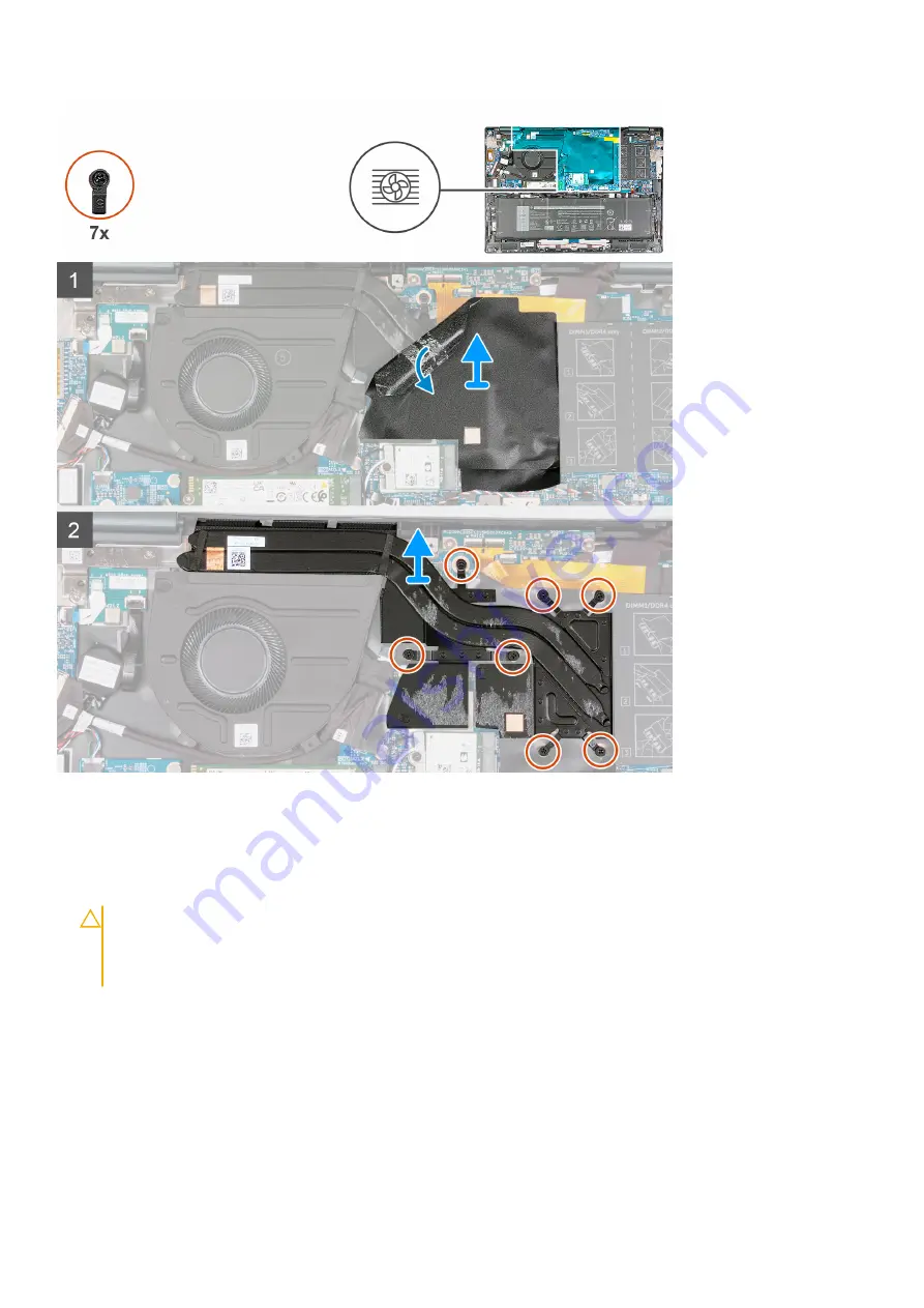
1. Peel off the Mylar that covers the heat sink.
2. In reverse sequential order (7>6>5>4>3>2>1), loosen the seven captive screws that secure the heat sink to the system

board.

3. Lift the heat sink off the system board.

CAUTION:

 Do not use an alcohol wipe to clean the thermal grease, the alcohol solution from the wipes will

dissolve the Element 31 grease into conductive metal particles. If these conductive metal particles come into
contact with the surface of the system board, it will cause the an electrical short when system is powered
on.

Installing the heat sink with discrete graphics

Prerequisites

If you are replacing a component, remove the existing component before performing the installation process.

40

Removing and installing components

Содержание Inspiron 16 7620

Страница 1: ...Inspiron 16 7620 2 in 1 Service Manual Regulatory Model P119F Regulatory Type P119F001 February 2022 Rev A00 ...

Страница 2: ...ential damage to hardware or loss of data and tells you how to avoid the problem WARNING A WARNING indicates a potential for property damage personal injury or death 2022 Dell Inc or its subsidiaries All rights reserved Dell EMC and other trademarks are trademarks of Dell Inc or its subsidiaries Other trademarks may be trademarks of their respective owners ...

Страница 3: ...tate drive 18 Wireless card 21 Fan 24 Side speakers 25 Front speakers 27 Coin cell battery 31 Battery 33 Heat sink 37 I O board 42 Power button board 43 Power button with fingerprint reader 45 Display assembly 47 Display board 50 System board 51 Palm rest and keyboard assembly 56 Chapter 3 Drivers and downloads 60 Chapter 4 BIOS setup 61 BIOS overview 61 Entering BIOS setup program 61 Navigation k...

Страница 4: ...5 Troubleshooting 70 Handling swollen Lithium ion batteries 70 Locate the Service Tag or Express Service Code of your Dell computer 70 System diagnostic lights 71 SupportAssist diagnostics 72 Built in self test BIST 72 Recovering the operating system 72 WiFi power cycle 73 Backup media and recovery options 73 Chapter 6 Getting help and contacting Dell 74 4 Contents ...

Страница 5: ...ng inside your computer ground yourself by touching an unpainted metal surface such as the metal at the back of the computer While you work periodically touch an unpainted metal surface to dissipate static electricity which could harm internal components CAUTION When you disconnect a cable pull it by its connector or its pull tab not the cable itself Some cables have connectors with locking tabs o...

Страница 6: ...the system and all attached peripherals Disconnect the system and all attached peripherals from AC power Disconnect all network cables telephone and telecommunications lines from the system Use an ESD field service kit when working inside any to avoid electrostatic discharge ESD damage After removing any system component carefully place the removed component on an anti static mat Wear shoes with n...

Страница 7: ...atic mat your wrist strap should be snug and the bonding wire should be connected to the mat and to any bare metal on the system being worked on Once deployed properly service parts can be removed from the ESD bag and placed directly on the mat ESD sensitive items are safe in your hand on the ESD mat in the system or inside a bag Wrist Strap and Bonding Wire The wrist strap and bonding wire can be...

Страница 8: ...d protective anti static mat at all times when servicing Dell products In addition it is critical that technicians keep sensitive parts separate from all insulator parts while performing service and that they use anti static bags for transporting sensitive components Transporting sensitive components When transporting ESD sensitive components such as replacement parts or parts to be returned to De...

Страница 9: ...crews and correct screw type is restored when the component is replaced NOTE Some computers have magnetic surfaces Ensure that the screws are not left attached to such surfaces when replacing a component NOTE Screw color may vary with the configuration ordered Table 1 Screw list Component Screw type Quantity Screw image Base cover M2x4 6 Base cover Captive screw 3 M 2 2230 mounting bracket M2x2 1 ...

Страница 10: ... 2 Power button board M2x3 2 Power button with fingerprint reader M2x2 5 2 Display hinges M2 5x4 5 Display board M2x2 2 USB Type C bracket M2x4 2 System board M2x2 1 System board M2x3 2 Major components of Inspiron 7620 2 in 1 The following image shows the major components of Inspiron 7620 2 in 1 10 Removing and installing components ...

Страница 11: ...ont speakers 6 Side speakers 7 2280 solid state drive 8 2230 solid state drive 9 Battery 10 Palm rest and keyboard assembly 11 Display assembly 12 Side speaker board 13 Coin cell battery 14 I O board 15 Power button board Removing and installing components 11 ...

Страница 12: ... from your computer depending on the configuration you ordered Base cover Removing the base cover Prerequisites 1 Follow the procedure in Before working inside your computer NOTE Ensure that your computer is in Service Mode For more information see step 6 in Before working inside your computer About this task NOTE Before removing the base cover ensure that there is no SD card installed in the SD c...

Страница 13: ... screws M2x4 that secure the base cover to the palm rest and keyboard assembly 2 Loosen the three captive screws M2x7 5 that secure the base cover to the palm rest and keyboard assembly Removing and installing components 13 ...

Страница 14: ... the palm rest and keyboard assembly Installing the base cover Prerequisites If you are replacing a component remove the existing component before performing the installation process About this task The following image s indicate the location of the base cover and provides a visual representation of the installation procedure 14 Removing and installing components ...

Страница 15: ...secure the base cover to the palm rest and keyboard assembly Next steps 1 Follow the procedure in After working inside your computer Memory Removing the memory Prerequisites 1 Follow the procedure in Before working inside your computer 2 Remove the base cover About this task The following image s indicate the location of the memory and provides a visual representation of the removal procedure Remo...

Страница 16: ...m board NOTE Your computer may have up to two memory modules installed Repeat steps 1 to 3 if there is a second memory module installed Installing the memory Prerequisites If you are replacing a component remove the existing component before performing the installation process About this task The following image s indicate the location of the memory and provides a visual representation of the inst...

Страница 17: ...y module into the memory module slot on the system board 4 Press down on the memory module till the securing clips click locking the memory module in place NOTE Repeat steps 1 to 4 for each memory module being installed into your computer Next steps 1 Install the base cover 2 Follow the procedure in After working inside your computer Removing and installing components 17 ...

Страница 18: ... provides a visual representation of the removal procedure Steps 1 Peel the Mylar that secures the M 2 2230 solid state drive to the M 2 slot on the system board 2 Remove the screw M2x2 that secures the M 2 2230 solid state drive mounting bracket to the system board 3 Slide and lift the M 2 2230 solid state drive assembly off the system board 4 Flip over the M 2 2230 solid state drive assembly 5 R...

Страница 19: ...mbly 4 Align the notch on the M 2 2230 solid state drive with the tab on the M 2 card slot on the system board 5 Slide the M 2 2230 solid state drive into the M 2 card slot on the system board 6 Replace the screw M2x2 that secures the M 2 2230 solid state drive mounting bracket to the system board 7 Adhere the Mylar over the M 2 2230 solid state drive and M 2 slot on the system board Next steps 1 ...

Страница 20: ...system board 2 Lift the M 2 2280 solid state drive off the system board Installing the 2280 solid state drive Prerequisites If you are replacing a component remove the existing component before performing the installation process About this task NOTE This procedure applies if you are installing a M 2 2280 solid state drive NOTE Supported card configurations M 2 2230 solid state drive M 2 2230 moun...

Страница 21: ... state drive to the system board Next steps 1 Install the base cover 2 Follow the procedure in After working inside your computer Wireless card Removing the wireless card Prerequisites 1 Follow the procedure in Before working inside your computer 2 Remove the base cover About this task The following image s indicate the location of the wireless card and provides a visual representation of the remo...

Страница 22: ...d 4 Slide and remove the wireless card from the M 2 card slot on the system board Installing the wireless card Prerequisites If you are replacing a component remove the existing component before performing the installation process About this task The following image s indicate the location of the wireless card and provides a visual representation of the installation procedure 22 Removing and insta...

Страница 23: ...te triangle Auxiliary Black AUX black triangle 2 Place the wireless card bracket on the wireless card 3 Align the notch on the wireless card with the tab on the M 2 card slot on the system board 4 Slide the wireless card into the M 2 card slot on the system board 5 Replace the screw M2x3 that secures the wireless card and wireless card bracket to the system board Next steps 1 Install the base cove...

Страница 24: ...em board 2 Disconnect the fan cable from the system board 3 Remove the two screws M2x3 that secure the fan to the palm rest and keyboard assembly 4 Lift the fan off the palm rest and keyboard assembly Installing the fan Prerequisites If you are replacing a component remove the existing component before performing the installation process About this task The following image s indicate the location ...

Страница 25: ...rd 5 Adhere the tape that secures the fan cable to the system board Next steps 1 Install the base cover 2 Follow the procedure in After working inside your computer Side speakers Removing the side speakers Prerequisites 1 Follow the procedure in Before working inside your computer 2 Remove the base cover About this task The following image s indicate the location of the side speakers and provides ...

Страница 26: ...ble from the routing guide on the palm rest and keyboard assembly 9 Remove the side speaker cable from the routing guides on the palm rest and keyboard assembly 10 Peel the tapes that secure the side speaker cable to the system board and palm rest and keyboard assembly 11 Disconnect the side speaker cable from the side speaker board 12 Lift the side speakers and its cable off the palm rest and key...

Страница 27: ...ect the side speaker board cable to the side speaker board 7 Route the front speaker cable through the routing guides on the system board 8 Connect the front speaker cable to the system board 9 Connect the keyboard backlight cable to the system board and close the latch 10 Connect the keyboard cable to the system board and close the latch 11 Connect the touchpad cable to the system board and close...

Страница 28: ...es securing the front speaker cable to the palm rest and keyboard assembly 4 Lift the speakers and its cable off the palm rest and keyboard assembly Installing the front speakers 4 cell battery 64 Wh Prerequisites If you are replacing a component remove the existing component before performing the installation process About this task NOTE This procedure only applies if you re installing the front ...

Страница 29: ...bly 4 Conect the front speaker cable to the system board Next steps 1 Install the base cover 2 Follow the procedure in After working inside your computer Removing the front speakers 6 cell battery 87 Wh Prerequisites 1 Follow the procedure in Before working inside your computer 2 Remove the base cover About this task NOTE This procedure only applies for computers shipped with a 6 cell battery 87 W...

Страница 30: ...d keyboard assembly Installing the front speakers 6 cell battery 87 Wh Prerequisites If you are replacing a component remove the existing component before performing the installation process About this task NOTE This procedure only applies if you re installing the front speaker for a computer with a 6 cell battery 87 Wh installed The following image s indicate the location of the front speakers 6 ...

Страница 31: ...he system board Next steps 1 Install the base cover 2 Follow the procedure in After working inside your computer Coin cell battery Removing the coin cell battery Prerequisites 1 Follow the procedure in Before working inside your computer 2 Remove the base cover About this task NOTE Removing the coin cell battery resets the BIOS setup program s settings to default It is recommended that you note th...

Страница 32: ...he coin cell battery from the palm rest and keyboard assembly Installing the coin cell battery Prerequisites If you are replacing a component remove the existing component before performing the installation process About this task The following image s indicate the location of the coin cell battery and provides a visual representation of the installation procedure 32 Removing and installing compon...

Страница 33: ...ving it Disconnect the AC power adapter from the system and operate the computer solely on battery power the battery is fully discharged when the computer no longer turns on when the power button is pressed Do not crush drop mutilate or penetrate the battery with foreign objects Do not expose the battery to high temperatures or disassemble battery packs and cells Do not apply pressure to the surfa...

Страница 34: ...e procedure in Before working inside your computer 2 Remove the base cover About this task NOTE This procedures only applies for computers shipped with a 4 cell battery 64 Wh installed The following image s indicate the location of the 4 cell battery 64 Wh and provides a visual representation of the removal procedure Steps 1 Disconnect the battery cable from the system board NOTE This step is appl...

Страница 35: ... Replace the five screws M2x3 that secure the 4 cell battery to the palm rest and keyboard assembly 4 Connect the battery cable to the system board Next steps 1 Install the base cover 2 Follow the procedure in After working inside your computer Removing the 6 cell battery 87 Wh Prerequisites 1 Follow the procedure in Before working inside your computer 2 Remove the base cover About this task NOTE ...

Страница 36: ...lm rest and keyboard assembly Installing the 6 cell battery 87 Wh Prerequisites If you are replacing a component remove the existing component before performing the installation process About this task NOTE This procedures only applies if you are installing a 6 cell battery 87 Wh into your computer The following image s indicate the location of the 6 cell battery 87 Wh and provides a visual repres...

Страница 37: ...ics Prerequisites 1 Follow the procedure in Before working inside your computer 2 Remove the base cover About this task NOTE The heat sink may become hot during normal operation Allow sufficient time for the heat sink to cool before you touch it NOTE For maximum cooling of the processor do not touch the heat transfer areas on the heat sink The oils in your skin can reduce the heat transfer capabil...

Страница 38: ... short when system is powered on Installing the heat sink without discrete graphics Prerequisites If you are replacing a component remove the existing component before performing the installation process About this task NOTE If either the system board or the fan and heat sink assembly is replaced use the thermal grease provided in the kit to ensure that thermal conductivity is achieved NOTE This p...

Страница 39: ...n Before working inside your computer 2 Remove the base cover About this task NOTE The heat sink may become hot during normal operation Allow sufficient time for the heat sink to cool before you touch it NOTE For maximum cooling of the processor do not touch the heat transfer areas on the heat sink The oils in your skin can reduce the heat transfer capability of the thermal grease NOTE This proced...

Страница 40: ...l grease the alcohol solution from the wipes will dissolve the Element 31 grease into conductive metal particles If these conductive metal particles come into contact with the surface of the system board it will cause the an electrical short when system is powered on Installing the heat sink with discrete graphics Prerequisites If you are replacing a component remove the existing component before ...

Страница 41: ...he location of the heat sink with discrete graphics and provides a visual representation of the installation procedure Steps 1 Place the heat sink on the system board 2 Align the captive screws on the heat sink to the screw holes on the system board 3 In sequential order 1 2 3 4 5 6 7 tighten the seven captive screws that secure the heat sink to the system board 4 Adhere the Mylar to the heat sink...

Страница 42: ...emoval procedure Steps 1 Remove the two screws M2 5x4 that secure the left display hinge to the system board 2 Pry open the left display hinge at an angle of 90 degrees 3 Lift the latch and disconnect the I O board cable from the I O board 4 Disconnect the coin cell battery cable from the I O board 5 Peel the tape that covers the screw on the I O board 6 Remove the two screws M2x3 that secure the ...

Страница 43: ... the I O board 5 Connect the coin cell battery to the I O board 6 Connect the I O board cable to the I O board and close the latch 7 Close the left display hinge and align the screw holes on the left display hinge with the screw holes on the I O board 8 Replace the two screws M2 5x4 that secure the left display hinge to the palm rest and keyboard assembly Next steps 1 Install the base cover 2 Foll...

Страница 44: ...e latch and disconnect the power button cable from the power button board 5 Remove the two screws M2x3 that secure the power button board to the palm rest and keyboard assembly 6 Lift the power button board off the palm rest and keyboard assembly Installing the power button board Prerequisites If you are replacing a component remove the existing component before performing the installation process...

Страница 45: ...he left display hinge with the screw holes on the I O board 7 Replace the two screws M2 5x4 that secure the left display hinge to the palm rest and keyboard assembly Next steps 1 Install the base cover 2 Follow the procedure in After working inside your computer Power button with fingerprint reader Removing the power button with fingerprint reader Prerequisites 1 Follow the procedure in Before wor...

Страница 46: ... keyboard assembly Installing the power button with fingerprint reader Prerequisites If you are replacing a component remove the existing component before performing the installation process About this task The following image s indicate the location of the power button with fingerprint reader and provides a visual representation of the installation procedure 46 Removing and installing components ...

Страница 47: ...l the power button board 2 Install the IO board 3 Install the base cover 4 Follow the procedure in After working inside your computer Display assembly Removing the display assembly Prerequisites 1 Follow the procedure in Before working inside your computer 2 Remove the base cover About this task The following image s indicate the location of the display assembly and provides a visual representatio...

Страница 48: ...d disconnect the display cable from the display board 6 Peel the tapes that secure the display cable to the palm rest and keyboard assembly 7 Peel the tape that secures the display cable connector latch to the system board 8 Lift the latch and disconnect the display cable from the system board 9 Gently lift the palm rest and keyboard assembly off the display assembly CAUTION To avoid damaging the ...

Страница 49: ...ut this task The following image s indicate the location of the display assembly and provides a visual representation of the installation procedure Steps 1 Place the display assembly on a clean and flat surface with the display panel facing up 2 Gently place the palm rest and keyboard assembly under the display hinges Removing and installing components 49 ...

Страница 50: ...nd keyboard assembly 9 Close the left display hinge and align the screw holes on the left display hinge with the screw holes on the I O board 10 Replace the two screws M2 5x4 that secure the left display hinge to the palm rest and keyboard assembly Next steps 1 Install the base cover 2 Follow the procedure in After working inside your computer Display board Removing the display board Prerequisites...

Страница 51: ... the screw holes on the display board with the screw holes on the palm rest and keyboard assembly 3 Replace the two screws M2x2 that secure the display board to the palm rest and keyboard assembly 4 Connect the display cable to the display board and close the latch Next steps 1 Install the base cover 2 Follow the procedure in After working inside your computer System board Removing the system boar...

Страница 52: ...backlight cable connnector 2 Display cable connector 3 Keyboard backlight cable connector 4 Keyboard cable connector 5 Touchpad cable connector 6 Battery cable connector 7 Front speaker cable connector 8 Side speaker board cable connector 9 I O board cable connector 10 Fan cable connector The following image s indicate the location of the system board and provides a visual representation of the re...

Страница 53: ... 6 Lift the latch and disconnect the display cable from the system board 7 Peel the tape that covers the USB Type C bracket 8 Remove the two screws M2x4 that secure the USB Type C bracket to the system board 9 Lift the USB Type C bracket off the system board 10 Lift the latch and disconnect the keyboard backlight cable from the system board 11 Lift the latch and disconnect the keyboard cable from ...

Страница 54: ...e the screw M2x3 that secures the system board to the palm rest and keyboard assembly 23 Remove the screw M2x2 that secures the system board to the palm rest and keyboard assembly 24 Lift the system board off the palm rest and keyboard assembly Installing the system board Prerequisites If you are replacing a component remove the existing component before performing the installation process About t...

Страница 55: ...embly 3 Replace the screw M2x3 that secures the system board to the palm rest and keyboard assembly 4 Replace the screw M2x2 that secures the system board to the palm rest and keyboard assembly 5 Connect the fan cable to the system board 6 Adhere the tape that secures the fan cable to the system board 7 Connect the I O board cable to the system board and close the latch 8 Adhere the tape that secu...

Страница 56: ...st and keyboard assembly 25 Connect the display backlight cable to the system board and close the latch 26 Adhere the tape that secures the display backlight cable to the system board Next steps 1 Install the display board 2 Install the heat sink without discrete graphics or heat sink with discrete graphics whichever applicable 3 Install the wireless card 4 Install the 2230 solid state drive or 22...

Страница 57: ...e the entire assembly palm rest keyboard wireless antenna modules touchpad The following image s indicate the location of the palm rest and keyboard assembly and provides a visual representation of the removal procedure For computers with a 4 cell battery installed 64 Wh For computers with a 6 cell battery installed 87 Wh Removing and installing components 57 ...

Страница 58: ... About this task NOTE The replacement palm rest and keyboard assembly comes pre assembled with the following components palm rest keyboard wireless antenna modules touchpad The following image s indicate the location of the palm rest and keyboard assembly and provides a visual representation of the installation procedure For computers with a 4 cell battery installed 64 Wh For computers with a 6 ce...

Страница 59: ...tall the system board NOTE The system board can be replaced with the following components pre attached heat sink memory solid state drive 2 Install the side speakers 3 Install the display board 4 Install the display assembly 5 Install the power button 6 Install the power button board 7 Install the IO board 8 Install the fan 9 Install the front speakers 4 cell battery or front speakers 6 cell batte...

Страница 60: ...rivers and downloads When troubleshooting downloading or installing drivers it is recommended that you read the Dell Knowledge Based article Drivers and Downloads FAQ 000123347 3 60 Drivers and downloads ...

Страница 61: ...g or disabling base devices BIOS overview The BIOS manages data flow between the computer s operating system and attached devices such as hard disk video adapter keyboard mouse and printer Entering BIOS setup program Steps 1 Turn on your computer 2 Press F2 immediately to enter the BIOS setup program NOTE If you wait too long and the operating system logo appears continue to wait until you see the...

Страница 62: ...Depending on this computer and its installed devices the items that are listed in this section may or may not be displayed Table 4 System setup options System information menu Overview BIOS Version Displays the BIOS version number Service Tag Displays the Service Tag of the computer Asset Tag Displays the Asset Tag of the computer Manufacture Date Displays the manufacture date of the computer Owne...

Страница 63: ...the technology that is used for the memory DIMM A Size Displays the memory configuration of DIMM A DIMM B Size Displays the memory configuration of DIMM B DEVICES Panel Type Displays the Panel Type of the computer Video Controller Displays the integrate graphics information of the computer Video Memory Displays the video memory information of the computer Wi Fi Device Displays the Wi Fi device ins...

Страница 64: ...er selected file Delete will delete the selected key Reset All Keys will reset all four keys to their default settings By default PK security key database is selected By default Save to File is selected Table 6 System setup options Integrated Devices menu Integrated Devices Date Time Date Sets the computer date in MM DD YYYY format Changes to the date take effect immediately Time Sets the computer...

Страница 65: ...ds menu Passwords Admin Password Enables the user to set change or delete the administrator admin password The admin password enables several security features System Password Enables the user to set change or delete the system password Internal HDD 1 Password Enables the user to set change or delete the Internal HDD 1 password Table 10 System setup options Update Recovery menu Update Recovery Sup...

Страница 66: ...ware will always halt the computer Table 13 System setup options System Logs menu System Logs BIOS Event Log Clear Bios Event Log Select keep or clear BIOS events Default Keep Thermal Event Log Clear Thermal Event Log Select keep or clear Thermal events Default Keep Power Event Log Clear POWER Event Log Select keep or clear Power events Default Keep System and setup password Table 14 System and se...

Страница 67: ...n the System Setup before attempting to delete or change the existing System and or Setup password You cannot delete or change an existing System or Setup password if the Password Status is Locked About this task To enter the System Setup press F12 immediately after a power on or reboot Steps 1 In the System BIOS or System Setup screen select System Security and press Enter The System Security scr...

Страница 68: ... to download the latest BIOS setup program file 2 Create a bootable USB drive For more information see the knowledge base article 000145519 at www dell com support 3 Copy the BIOS setup program file to the bootable USB drive 4 Connect the bootable USB drive to the computer that needs the BIOS update 5 Restart the computer and press F12 6 Select the USB drive from the One Time Boot Menu 7 Type the ...

Страница 69: ...not turn off the computer during the BIOS update process The computer may not boot if you turn off your computer Steps 1 From a turn off state insert the USB drive where you copied the flash into a USB port of the computer 2 Turn on the computer and press F12 to access the One Time Boot Menu select BIOS Update using the mouse or arrow keys then press Enter The flash BIOS menu is displayed 3 Click ...

Страница 70: ...cks and cells Do not apply pressure to the surface of the battery Do not bend the battery Do not use tools of any type to pry on or against the battery If a battery gets stuck in a device as a result of swelling do not try to free it as puncturing bending or crushing a battery can be dangerous Do not attempt to reassemble a damaged or swollen battery into a laptop Swollen batteries that are covere...

Страница 71: ...battery status light patterns and associated problems Table 15 LED codes Diagnostic light codes Amber white Problem description 1 1 TPM detection failure 1 2 Unrecoverable SPI flash failure 2 1 Processor failure 2 2 System board BIOS or Read Only Memory ROM failure 2 3 No memory or Random Access Memory RAM detected 2 4 Memory or Random Access Memory RAM failure 2 5 Invalid memory installed 2 6 Sys...

Страница 72: ... board embedded controller EC failures M BIST must be manually initiated before POST and can also run on a dead system 2 L BIST L BIST is an enhancement to the single LED error code diagnostics and is automatically initiated during POST 3 LCD BIST LCD BIST is an enhanced diagnostic test that is introduced through Preboot System Assessment PSA on legacy systems Table 16 Functions M BIST L BIST Purp...

Страница 73: ...s a WiFi power cycle procedure may be performed The following procedure provides the instructions on how to conduct a WiFi power cycle NOTE Some ISPs Internet Service Providers provide a modem router combo device Steps 1 Turn off your computer 2 Turn off the modem 3 Turn off the wireless router 4 Wait for 30 seconds 5 Turn on the wireless router 6 Turn on the modem 7 Turn on your computer Backup m...

Страница 74: ...r Express Service Code at www dell com support For more information on how to find the Service Tag for your computer see Locate the Service Tag on your computer Dell knowledge base articles for a variety of computer concerns 1 Go to www dell com support 2 On the menu bar at the top of the Support page select Support Knowledge Base 3 In the Search field on the Knowledge Base page type the keyword t...

Отзывы: