background image

Solid-state drive—M.2 slot one

Removing the M.2 2230 solid-state drive

Prerequisites

1. Follow the procedure in 

Before working inside your computer

.

2. Enter 

Service Mode

.

3. Remove the 

base cover

.

About this task

NOTE:

 This procedure applies only to computers shipped with an M.2 2230 solid-state drive installed in M.2 slot one.

NOTE:

 The M.2 card installed on M.2 slot one will depend on the configuration ordered. Supported card configurations on

the M.2 card slot:

M.2 2230 solid-state drive + M.2 2230 mounting bracket

M.2 2280 solid-state drive

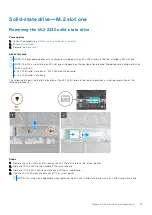
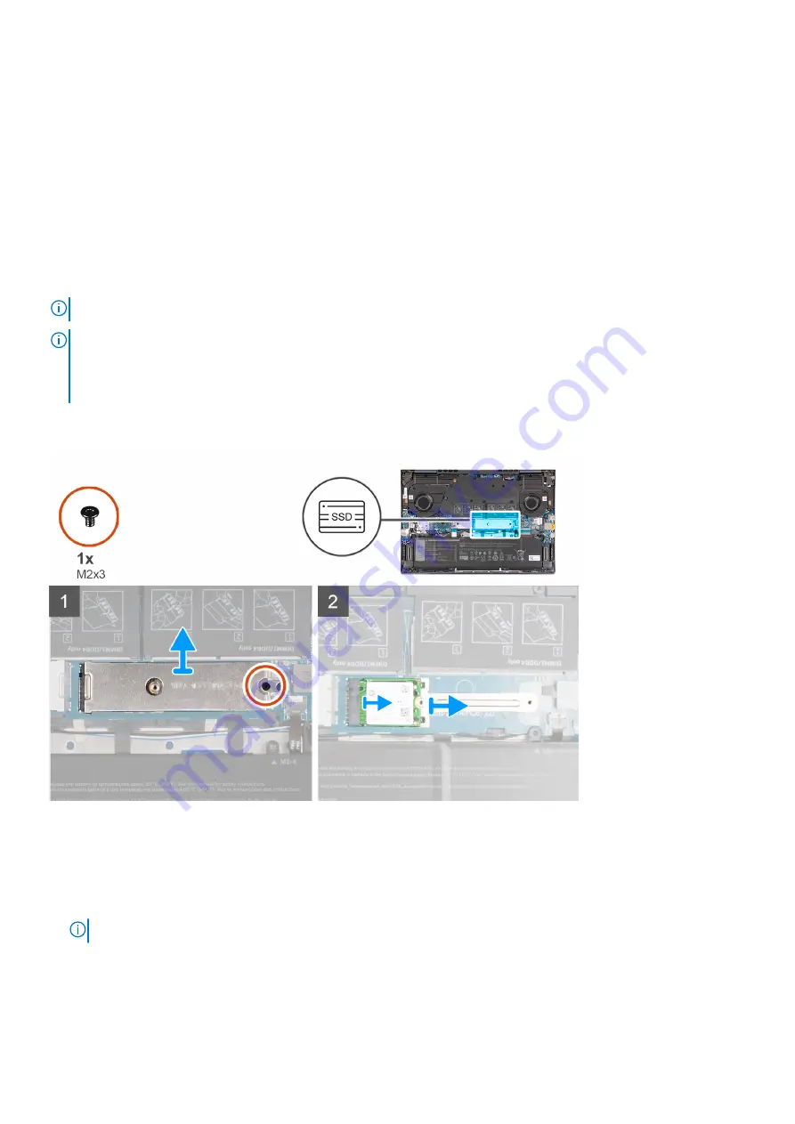
The following image(s) indicate the location of the M.2 2230 solid-state drive and provides a visual representation of the
removal procedure.

Steps

1. Remove the screw (M2x3) that secures the M.2 thermal shield to the system board.
2. Slide and lift the M.2 thermal shield off the system board.
3. Slide and lift the M.2 2230 solid-state drive off the system board.
4. Peel the M.2 2230 mounting bracket off the system board.

NOTE:

 This step is only applicable when replacing the M.2 2230 solid-state drive with a M.2 2280 solid-state drive.

Removing and installing components

19

Содержание Inspiron 16 7610

Страница 1: ...Inspiron 16 7610 Service Manual for computers with two fans Regulatory Model P107F Regulatory Type P107F001 July 2021 Rev A01 ...

Страница 2: ...ential damage to hardware or loss of data and tells you how to avoid the problem WARNING A WARNING indicates a potential for property damage personal injury or death 2021 Dell Inc or its subsidiaries All rights reserved Dell EMC and other trademarks are trademarks of Dell Inc or its subsidiaries Other trademarks may be trademarks of their respective owners ...

Страница 3: ...dule 16 Removing the memory 16 Installing the memory 17 Solid state drive M 2 slot one 19 Removing the M 2 2230 solid state drive 19 Installing the M 2 2230 solid state drive 20 Removing the M 2 2280 solid state drive 21 Installing the M 2 2280 solid state drive 21 Solid state drive M 2 slot two 22 Removing the M 2 2230 solid state drive 22 Installing the M 2 2230 solid state drive 23 Wireless car...

Страница 4: ...with fingerprint reader 50 Installing the power button with fingerprint reader 51 System board 52 Removing the system board 52 Installing the system board 53 Speakers 56 Removing the speakers 56 Installing the speakers 57 Palm rest and keyboard assembly 58 Removing the palm rest and keyboard assembly 58 Installing the palm rest and keyboard assembly 59 Chapter 4 Drivers and downloads 60 Chapter 5 ...

Страница 5: ...ries 73 Locate the Service Tag or Express Service Code of your Dell computer 73 System diagnostic lights 74 SupportAssist On board Diagnostics 75 Recovering the operating system 75 Updating the BIOS using the USB drive in Windows 75 Updating the BIOS in Windows 76 WiFi power cycle 76 Chapter 7 Getting help and contacting Dell 77 Contents 5 ...

Страница 6: ...onents on your computer This manual is only applicable for Inspiron 16 7610 computers with two fans installed This two fan configuration is only available in systems where one of the following graphic card configurations are shipped with your computer Integrated Intel UHD Graphics only NVIDIA GeForce GTX 1650 NVIDIA GeForce RTX 3050 NVIDIA GeForce RTX 3050 Ti To physically identify if your compute...

Страница 7: ...from the system board To enter Service Mode 1 Shut down your computer and disconnect the AC adapter 2 Hold B key on the keyboard and press the power button for 3 seconds or until the Dell logo appears on the screen 3 Press any key to continue NOTE If the power adapter has not been disconnected a message prompting you to remove the AC adapter appears on the screen Remove the AC adapter and then pre...

Страница 8: ...protection ESD is a major concern when you handle electronic components especially sensitive components such as expansion cards processors memory DIMMs and system boards Very slight charges can damage circuits in ways that may not be obvious such as intermittent problems or a shortened product life span As the industry pushes for lower power requirements and increased density ESD protection is an ...

Страница 9: ... plug the wrist strap s bonding wire into the tester while it is strapped to your wrist and push the button to test A green LED is lit if the test is successful a red LED is lit and an alarm sounds if the test fails Insulator Elements It is critical to keep ESD sensitive devices such as plastic heat sink casings away from internal parts that are insulators and often highly charged Working Environm...

Страница 10: ...e load Avoid twisting your body and back 6 Follow the same techniques in reverse to set the load down Exiting Service Mode Service Mode allows users to immediately cut off electricity from the computer and conduct repairs without disconnecting the battery cable from the system board To exit Service Mode 1 Connect the AC adapter to the power adapter port on your computer 2 Press the power button to...

Страница 11: ...ers have magnetic surfaces Ensure that the screws are not left attached to such surfaces when replacing a component NOTE Screw color may vary with the configuration ordered Table 1 Screw list Component Secured to Screw type Quantity Screw image Base cover Palm rest and keyboard assembly M2x4 7 Base cover Palm rest and keyboard assembly M2x8 5 captive 2 Battery Palm rest and keyboard assembly M2x3 ...

Страница 12: ...rd Palm rest and keyboard assembly M2x2 1 System board Palm rest and keyboard assembly M2x3 2 Major components of Inspiron 16 7610 The following image shows the major components of Inspiron 16 7610 1 Base cover 2 Power adapter port 3 Right fan 4 M 2 2230 solid state drive if installed 5 M 2 2280 solid state drive if installed 6 Memory 7 Battery 8 Touchpad 9 Display assembly 10 Wireless card and wi...

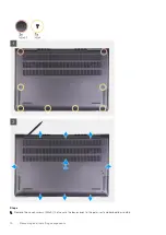
Страница 13: ...e options Base cover Removing the base cover Prerequisites 1 Follow the procedure in Before working inside your computer 2 Enter Service Mode About this task NOTE Before removing the base cover ensure that there is no micro SD card installed in the micro SD card slot on your computer The following image s indicate the location of the base cover and provides a visual representation of the removal p...

Страница 14: ...Steps 1 Remove the seven screws M2x4 that secure the base cover to the palm rest and keyboard assembly 14 Removing and installing components ...

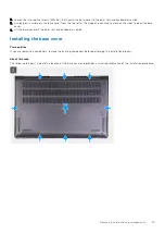
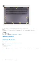
Страница 15: ... to open the base cover 4 Lift the base cover off the palm rest and keyboard assembly Installing the base cover Prerequisites If you are replacing a component remove the existing component before performing the installation process About this task The following image s indicate the location of the base cover and provides a visual representation of the installation procedure Removing and installing...

Страница 16: ... the palm rest and keyboard assembly Next steps 1 Exit Service Mode 2 Follow the procedure in After working inside your computer Memory module Removing the memory Prerequisites 1 Follow the procedure in Before working inside your computer 2 Enter Service Mode 3 Remove the base cover About this task The following image s indicate the location of the memory and provides a visual representation of th...

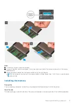
Страница 17: ...m board NOTE Your computer may have up to two memory modules installed Repeat steps 1 to 3 if there is a second memory module installed Installing the memory Prerequisites If you are replacing a component remove the existing component before performing the installation process About this task The following image s indicate the location of the memory and provides a visual representation of the inst...

Страница 18: ...nto the memory module slot on the system board 4 Press down on the memory module till the securing clips click locking the memory module in place NOTE Repeat steps 1 to 4 for each memory module being installed into your computer Next steps 1 Install the base cover 2 Exit Service Mode 3 Follow the procedure in After working inside your computer 18 Removing and installing components ...

Страница 19: ...rd slot M 2 2230 solid state drive M 2 2230 mounting bracket M 2 2280 solid state drive The following image s indicate the location of the M 2 2230 solid state drive and provides a visual representation of the removal procedure Steps 1 Remove the screw M2x3 that secures the M 2 thermal shield to the system board 2 Slide and lift the M 2 thermal shield off the system board 3 Slide and lift the M 2 ...

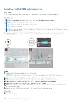
Страница 20: ...llation procedure Steps 1 Adhere the M 2 2230 mounting bracket to the system board NOTE Only perform this step when replacing a M 2 2280 solid state drive with a M 2 2230 solid state drive 2 Align the screw hole of the M 2 2230 mounting bracket to the screw hole on the system board 3 Align the notch on the M 2 2230 solid state drive with the tab on the M 2 card slot on the system board 4 Align the...

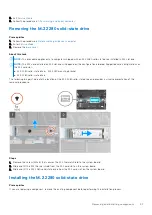
Страница 21: ...e M 2 card slot M 2 2230 solid state drive M 2 2230 mounting bracket M 2 2280 solid state drive The following image s indicate the location of the M 2 2280 solid state drive and provides a visual representation of the removal procedure Steps 1 Remove the screw M2x3 that secures the M 2 thermal shield to the system board 2 Slide and lift the M 2 thermal shield from the M 2 card slot on the system b...

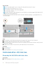
Страница 22: ...ure Steps 1 Align the notch on the M 2 2280 solid state drive with the tab on the M 2 card slot on the system board 2 Slide the M 2 2280 solid state drive into the M 2 card slot on the system board 3 Slide the tab on the M 2 thermal shield into the M 2 card slot and align the screw hole on the thermal shield to the screw hole on the system board 4 Replace the screw M2x3 that secures the M 2 2280 s...

Страница 23: ...0 thermal shield to the system board 2 Slide and lift the M 2 2230 thermal shield off the system board 3 Slide and lift the M 2 2230 solid state drive off the system board Installing the M 2 2230 solid state drive Prerequisites If you are replacing a component remove the existing component before performing the installation process About this task NOTE M 2 card slot two can only support an M 2 223...

Страница 24: ...rd 4 Replace the screw M2x3 that secures the M 2 2230 thermal shield to the system board Next steps 1 Install the base cover 2 Exit Service Mode 3 Follow the procedure in After working inside your computer Wireless card Removing the wireless card Prerequisites 1 Follow the procedure in Before working inside your computer 2 Enter Service Mode 3 Remove the base cover About this task The following im...

Страница 25: ...d 4 Slide and remove the wireless card from the M 2 card slot on the system board Installing the wireless card Prerequisites If you are replacing a component remove the existing component before performing the installation process About this task The following image s indicate the location of the wireless card and provides a visual representation of the installation procedure Removing and installi...

Страница 26: ...ard bracket on the wireless card 3 Align the notch on the wireless card with the tab on the M 2 card slot on the system board 4 Slide the wireless card into the M 2 card slot on the system board 5 Replace the screw M2x3 that secures the wireless card and wireless card bracket to the system board Next steps 1 Install the base cover 2 Exit Service Mode 3 Follow the procedure in After working inside ...

Страница 27: ...other system components If the battery gets stuck inside your computer as a result of swelling do not try to release it as puncturing bending or crushing a lithium ion battery can be dangerous In such an instance contact Dell technical support for assistance See www dell com contactdell Always purchase genuine batteries from www dell com or authorized Dell partners and resellers Swollen batteries ...

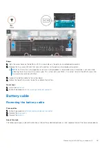
Страница 28: ...keyboard assembly Installing the battery Prerequisites If you are replacing a component remove the existing component before performing the installation process About this task NOTE This procedure applies to both 3 cell and 6 cell battery configurations that can be installed in your computer The following image s indicate the location of the battery and provides a visual representation of the inst...

Страница 29: ...all the M2x3 screws into the screw holes marked with M2x4 3 Connect the battery cable to the system board 4 Adhere the tape that secures the battery cable to the battery Next steps 1 Install the base cover 2 Follow the procedure in After working inside your computer Battery cable Removing the battery cable Prerequisites 1 Follow the procedure in Before working inside your computer 2 Remove the bas...

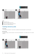
Страница 30: ...f the battery Installing the battery cable Prerequisites If you are replacing a component remove the existing component before performing the installation process About this task The following image s indicate the location of the battery cable and provides a visual representation of the installation procedure 30 Removing and installing components ...

Страница 31: ...r working inside your computer Display assembly Removing the display assembly Prerequisites 1 Follow the procedure in Before working inside your computer 2 Enter Service Mode 3 Remove the base cover About this task The following image s indicate the location of the display assembly and provides a visual representation of the removal procedure Removing and installing components 31 ...

Страница 32: ...splay hinge at an angle of 90 degrees 4 Remove the three screws M2 5x5 that secure the left display hinge to the I O board 5 Pry open the left display hinge at an angle of 90 degrees 6 Gently lift the palm rest and keyboard assembly off the display assembly CAUTION To avoid damaging the display do not slide the palm rest and keyboard assembly over the display assembly 32 Removing and installing co...

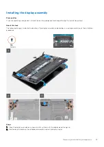
Страница 33: ...ut this task The following image s indicate the location of the display assembly and provides a visual representation of the installation procedure Steps 1 Place the display assembly on a clean and flat surface with the display panel facing up 2 Gently place the palm rest and keyboard assembly under the display hinges Removing and installing components 33 ...

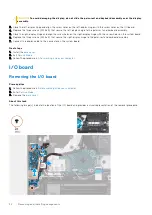
Страница 34: ...les on the system board 6 Replace the three screws M2 5x5 that secure the right display hinge to the palm rest and keyboard assembly 7 Connect the display cable to the connector on the system board Next steps 1 Install the base cover 2 Exit Service Mode 3 Follow the procedure in After working inside your computer I O board Removing the I O board Prerequisites 1 Follow the procedure in Before worki...

Страница 35: ...6 Lift the I O board off the palm rest and keyboard assembly Installing the I O board Prerequisites If you are replacing a component remove the existing component before performing the installation process About this task The following image s indicate the location of the I O board and provides a visual representation of the installation procedure Steps 1 Align the ports on the I O board to the sl...

Страница 36: ... Remove the battery About this task The following image s indicate the location of the touchpad and provides a visual representation of the removal procedure Steps 1 Open the latch and disconnect the touchpad cable from the touchpad 2 Remove the two screws M2x2 that secure the touchpad bracket to the palm rest and keyboard assembly 3 Lift the touchpad bracket off the palm rest and keyboard assembl...

Страница 37: ...uchpad alignment for your computer 3 Close the display and place the computer in the position shown 4 Replace the two screws M2x2 that secure the touchpad to the palm rest and keyboard assembly 5 Place the touchpad bracket on the touchpad 6 Align the screw holes on the touchpad bracket to the screw holes on the palm rest and keyboard assembly 7 Replace the two screws M2x2 that secure the touchpad ...

Страница 38: ...quisites 1 Follow the procedure in Before working inside your computer 2 Enter Service Mode 3 Remove the base cover About this task The following image s indicate the location of the left fan and provides a visual representation of the removal procedure Steps 1 Lift the corner of the Mylar that covers the system board 2 Disconnect the left fan cable from the system board 3 Remove the two screws M2...

Страница 39: ...sembly 3 Replace the two screws M2x4 that secure the fan to the palm rest and keyboard assembly 4 Lift the corner of the Mylar that covers the system board 5 Connect the fan cable to the system board Next steps 1 Install the base cover 2 Exit Service Mode 3 Follow the procedure in After working inside your computer Removing the right fan Prerequisites 1 Follow the procedure in Before working insid...

Страница 40: ...an off the palm rest and keyboard assembly Installing the right fan Prerequisites If you are replacing a component remove the existing component before performing the installation process About this task The following image s indicate the location of the right fan and provides a visual representation of the installation procedure 40 Removing and installing components ...

Страница 41: ... sink Removing the heat sink Prerequisites 1 Follow the procedure in Before working inside your computer 2 Enter Service Mode 3 Remove the base cover About this task CAUTION The heat sink may become hot during normal operation Allow sufficient time for the heat sink to cool before you touch it NOTE For maximum cooling of the processor do not touch the heat transfer areas on the heat sink The oils ...

Страница 42: ...stalling the heat sink Prerequisites If you are replacing a component remove the existing component before performing the installation process About this task NOTE If either the system board or the heat sink is replaced use the thermal grease provided in the kit to ensure that thermal conductivity is achieved The following image s indicate the location of the heat sink and provides a visual repres...

Страница 43: ...ation ordered Next steps 1 Install the base cover 2 Exit Service Mode 3 Follow the procedure in After working inside your computer Power adapter port Removing the power adapter port Prerequisites 1 Follow the procedure in Before working inside your computer 2 Enter Service Mode 3 Remove the base cover 4 Remove the left fan 5 Remove the heat sink About this task The following image s indicate the l...

Страница 44: ...o the palm rest and keyboard assembly 6 Remove the power adapter port cable from the routing guides on the palm rest and keyboard assembly 7 Remove the power adapter port from the palm rest and keyboard assembly Installing the power adapter port Prerequisites If you are replacing a component remove the existing component before performing the installation process About this task The following imag...

Страница 45: ...ht display hinge and align the screw holes on the right display hinge with the screw holes on the system board 6 Replace the three screws M2 5x5 that secures the right display hinge to the system board Next steps 1 Install the heat sink 2 Install the left fan 3 Install the base cover 4 Exit Service Mode 5 Follow the procedure in After working inside your computer Power button board Removing the po...

Страница 46: ... is only applicable for computers shipped with the optional fingerprint reader 4 Lift the power button board cable connector latch and disconnect the power button board cable from the I O board 5 Peel the tape that secures the power button with optional fingerprint reader cable and power button board cable to the palm rest and keyboard assembly 6 Remove the screw M2x3 that secures the power button...

Страница 47: ...e connector on the I O board and close the latch NOTE This step is only applicable for computers shipped with the optional fingerprint reader 5 Adhere the tape that secures the power button with optional fingerprint reader cable and power button board cable to the palm rest and keyboard assembly 6 Close the left display hinge and align the screw holes on the left display hinge with the screw holes...

Страница 48: ...n procedure Steps 1 Using the alignment posts place the power button with fingerprint reader into its slot on the palm rest and keyboard assembly 2 Replace the screw M2x3 that secures the power button with fingerprint reader to the palm rest and keyboard assembly Next steps 1 Install the power button board 2 Install the heat sink 3 Install the left fan 4 Install the base cover 5 Exit Service Mode ...

Страница 49: ...ower button board About this task The following image s indicate the location of the power button and provides a visual representation of the removal procedure Steps 1 Remove the screw M2x3 that secures the power button with fingerprint reader to the palm rest and keyboard assembly 2 Lift the power button with fingerprint reader off the palm rest and keyboard assembly Removing and installing compo...

Страница 50: ...fan 6 Remove the power button board About this task The following image s indicate the location of the power button with fingerprint reader and provides a visual representation of the removal procedure Steps 1 Remove the screw M2x3 that secures the power button with fingerprint reader to the palm rest and keyboard assembly 2 Lift the power button with fingerprint reader off the palm rest and keybo...

Страница 51: ...f the installation procedure Steps 1 Using the alignment posts place the power button with fingerprint reader into its slot on the palm rest and keyboard assembly 2 Replace the screw M2x3 that secures the power button with fingerprint reader to the palm rest and keyboard assembly Next steps 1 Install the power button board 2 Install the heat sink 3 Install the left fan 4 Install the base cover 5 E...

Страница 52: ... M 2 slot two 6 Remove the wireless card 7 Remove the battery 8 Remove the left fan 9 Remove the right fan 10 Remove the heat sink About this task The following image indicates the connectors on your system board 1 Display cable 2 Power adapter port cable 3 Keyboard backlight cable 4 Keyboard cable 5 Touchpad cable 6 Speaker cable 7 I O board cable The following image s indicate the location of th...

Страница 53: ...e system board 8 Disconnect the speaker cable from the system board 9 Lift the I O board cable connector latch and disconnect the I O board cable from the system board 10 Lift the Type C port bracket off the system board 11 Remove the two screws M2x3 that secure the system board to the palm rest and keyboard assembly 12 Remove the screw M2x2 that secures the system board to the palm rest and keybo...

Страница 54: ...d backlight cable 4 Keyboard cable 5 Touchpad cable 6 Speaker cable 7 I O board cable The following image s indicate the location of the system board and provides a visual representation of the installation procedure 54 Removing and installing components ...

Страница 55: ...nnect the keyboard backlight cable to the connector on the system board and close the latch 10 Connect the keyboard cable to the connector on the system board and close the latch 11 Connect the touchpad cable to the connector on the system board and close the latch 12 Connect the speaker cable to the system board 13 Connect the I O board cable to the connector on the system board and close the lat...

Страница 56: ...eft fan 8 Remove the right fan 9 Remove the heat sink 10 Remove the system board NOTE The system board can be removed with the heat sink solid state drives and memory installed About this task The following image s indicate the location of the speakers and provides a visual representation of the removal procedure Steps 1 Peel off the tapes that secure the speaker cable to the palm rest and keyboar...

Страница 57: ...ber grommets on the speaker 2 Route the speaker cable through the routing guides on the palm rest and keyboard assembly 3 Adhere the tapes that secure the speaker cable to the palm rest and keyboard assembly Next steps 1 Install the system board 2 Install the heat sink 3 Install the left fan 4 Install the right fan 5 Install the battery 6 Install the wireless card 7 Install the M 2 2230 solid stat...

Страница 58: ...emove the touchpad 10 Remove the display assembly 11 Remove the power button board 12 Remove the power button or power button with fingerprint whichever applicable 13 Remove the left fan 14 Remove the right fan 15 Remove the system board NOTE The system board can be removed with the heat sink solid state drives and memory installed 16 Remove the speakers About this task The following image s indic...

Страница 59: ...bly Next steps 1 Install the speakers 2 Install the system board 3 Install the left fan 4 Install the right fan 5 Install the power button or power button with fingerprint whichever applicable 6 Install the power button board 7 Install the display assembly 8 Install the touchpad 9 Install the IO board 10 Install the power adapter port 11 Install the battery 12 Install the wireless card 13 Install ...

Страница 60: ...rivers and downloads When troubleshooting downloading or installing drivers it is recommended that you read the Dell Knowledge Based article Drivers and Downloads FAQ SLN128938 4 60 Drivers and downloads ...

Страница 61: ...ling base devices Entering BIOS setup program Steps 1 Turn on your computer 2 Press F2 immediately to enter the BIOS setup program NOTE If you wait too long and the operating system logo appears continue to wait until you see the desktop Then turn off your computer and try again Navigation keys NOTE For most of the System Setup options changes that you make are recorded but do not take effect unti...

Страница 62: ... Overview BIOS Version Displays the BIOS version number Service Tag Displays the Service Tag of the computer Asset Tag Displays the Asset Tag of the computer Manufacture Date Displays the manufacture date of the computer Ownership Date Displays the ownership date of the computer Express Service Code Displays the express service code of the computer Ownership Tag Displays the ownership tag of the c...

Страница 63: ...mory Displays the video memory information of the computer Wi Fi Device Displays the Wi Fi device installed in the computer Native Resolution Displays the native resolution of the computer Video BIOS Version Displays the video BIOS version of the computer Audio Controller Displays the audio controller information of the computer Bluetooth Device Displays whether a Bluetooth device is installed in ...

Страница 64: ...puter date in MM DD YYYY format Changes to the date take effect immediately Time Sets the computer time in HH MM SS 24 hour format You can switch between 12 hour and 24 hour clock Changes to the time take effect immediately Camera Enable Camera Enables or disables the camera By default Enable Camera is selected Audio Enables or disables all integrated audio controller Default ON Enable Microphone ...

Страница 65: ...ange or delete the system password Internal HDD 1 Password Enables the user to set change or delete the Internal HDD 1 password Table 10 System setup options Update Recovery menu Update Recovery SupportAssist OS Recovery Enables or disables the boot flow for SupportAssist OS Recovery tool in the event of certain system error Default ON BIOSConnect Enables or disables cloud Service OS recovery if t...

Страница 66: ...vents Default Keep Power Event Log Clear POWER Event Log Select keep or clear Power events Default Keep Updating the BIOS in Windows Prerequisites It is recommended to update your BIOS System Setup when you replace the system board or if an update is available About this task NOTE If BitLocker is enabled it must be suspended before updating the system BIOS and then re enabled after the BIOS update...

Страница 67: ...tall For more information on this subject see Knowledge Article https www dell com support article sln153694 Updating your system BIOS using a USB flash drive About this task If the computer cannot load into Windows but there is still a need to update the BIOS download the BIOS file using another computer and save it to a bootable USB flash drive NOTE You must use a bootable USB flash drive For mo...

Страница 68: ...n the F12 One Time Boot Menu can use this function Updating from the One Time Boot Menu To update your BIOS from the F12 One Time boot menu you will need USB key formatted to the FAT32 file system key does not have to be bootable BIOS executable file that you downloaded from the Dell Support website and copied to the root of the USB key AC power adapter connected to the system Functional system ba...

Страница 69: ...3 The flash BIOS menu will open and then click the Flash from file 4 Select external USB device System setup 69 ...

Страница 70: ...5 Once the file is selected Double click the flash target file then press submit 6 Click the Update BIOS then system will reboot to flash the BIOS 70 System setup ...

Страница 71: ...e your computer CAUTION The password features provide a basic level of security for the data on your computer CAUTION Anyone can access the data stored on your computer if it is not locked and left unattended NOTE System and setup password feature is disabled Assigning a system setup password Prerequisites You can assign a new System or Admin Password only when the status is in Not Set About this ...

Страница 72: ...tem BIOS or System Setup screen select System Security and press Enter The System Security screen is displayed 2 In the System Security screen verify that Password Status is Unlocked 3 Select System Password alter or delete the existing system password and press Enter or Tab 4 Select Setup Password alter or delete the existing setup password and press Enter or Tab NOTE If you change the System and...

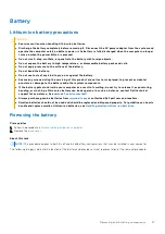
Страница 73: ...cks and cells Do not apply pressure to the surface of the battery Do not bend the battery Do not use tools of any type to pry on or against the battery If a battery gets stuck in a device as a result of swelling do not try to free it as puncturing bending or crushing a battery can be dangerous Do not attempt to reassemble a damaged or swollen battery into a laptop Swollen batteries that are covere...

Страница 74: ...es and recommended solutions are intended for Dell service technicians to troubleshoot problems You should only perform troubleshooting and repairs as authorized or directed by the Dell technical support team Damage due to servicing that is not authorized by Dell is not covered by your warranty Table 15 Diagnostic light codes Diagnostic light codes Amber white Problem description 1 1 TPM detection...

Страница 75: ...c devices require user interaction Ensure that you are present at the computer terminal when the diagnostic tests are performed For more information see SupportAssist Pre Boot System Performance Check Recovering the operating system When your computer is unable to boot to the operating system even after repeated attempts it automatically starts Dell SupportAssist OS Recovery Dell SupportAssist OS ...

Страница 76: ...ect the latest version of BIOS and click Download to download the BIOS file for your computer 7 After the download is complete browse the folder where you saved the BIOS update file 8 Double click the BIOS update file icon and follow the on screen instructions For more information see knowledge base article 000124211 at www dell com support WiFi power cycle About this task If your computer is unab...

Страница 77: ...ick Search to retrieve the related articles Learn and know the following information about your product Product specifications Operating system Setting up and using your product Data backup Troubleshooting and diagnostics Factory and system restore BIOS information See Me and My Dell at www dell com support manuals To locate the Me and My Dell relevant to your product identify your product through...

Отзывы: