background image

About this task

NOTE:

 This procedure applies only to computers shipped with a M.2 2280 solid-state drive installed.

NOTE:

 The M.2 card installed on your computer will depend on the configuration ordered. Supported card configurations on

the M.2 card slot:

M.2 2230 solid-state drive + 2230 mounting bracket

M.2 2280 solid-state drive

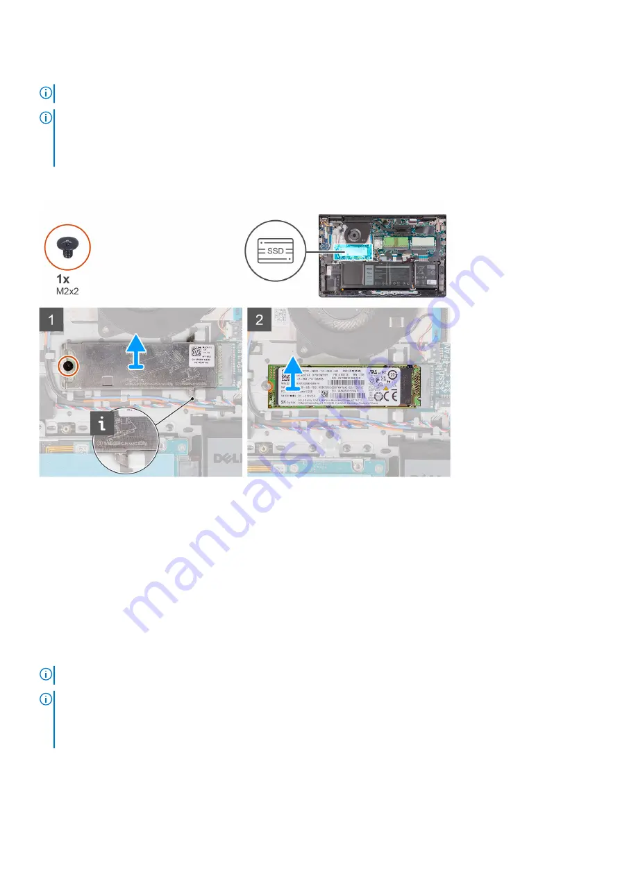
The following images indicate the location of the M.2 2280 solid-state drive and provides a visual representation of the removal
procedure.

Steps

1. Remove the (M2x2) screws that secure the M.2 thermal plate to the palmrest and keyboard assembly.
2. Lift the M.2 thermal plate from the palmrest and keyboard assembly.
3. Slide and remove the M.2 2280 solid-state drive from the M.2 card slot on the system board.

Installing the M.2 2280 solid-state drive

Prerequisites

If you are replacing a component, remove the existing component before performing the installation process.

About this task

NOTE:

 This procedure applies if you are installing a M.2 2280 solid-state drive.

NOTE:

 The M.2 card installed on your computer will depend on the configuration ordered. Supported card configurations on

the M.2 card slot:

M.2 2230 solid-state drive + 2230 mounting bracket

M.2 2280 solid-state drive

The following images indicate the location of the M.2 2280 solid-state drive and provides a visual representation of the
installation procedure.

Removing and installing components

23

Содержание Inspiron 15 3515 Series

Страница 1: ...Inspiron 15 3515 Service Manual Regulatory Model P112F Regulatory Type P112F005 June 2021 Rev A00 ...

Страница 2: ...tial damage to hardware or loss of data and tells you how to avoid the problem WARNING A WARNING indicates a potential for property damage personal injury or death 2020 2021 Dell Inc or its subsidiaries All rights reserved Dell EMC and other trademarks are trademarks of Dell Inc or its subsidiaries Other trademarks may be trademarks of their respective owners ...

Страница 3: ... cover 17 Battery 18 Lithium ion battery precautions 18 Removing the battery 19 Installing the battery 20 Solid state drive 21 Removing the M 2 2230 solid state drive 21 Installing the M 2 2230 solid state drive 21 Removing the M 2 2280 solid state drive 22 Installing the M 2 2280 solid state drive 23 Wireless card 24 Removing the wireless card 24 Installing the wireless card 25 Input Output board...

Страница 4: ...Installing the display bezel 52 Hinges 53 Removing the hinges 53 Installing the hinges 54 Display panel 56 Removing the display panel 56 Installing the display panel 58 Camera 60 Removing the camera module 60 Installing the camera module 61 Touchpad 61 Removing the touchpad 61 Installing the touchpad 62 System board 64 Removing the system board 64 Installing the system board 66 Power adapter port ...

Страница 5: ...pter 5 Troubleshooting 80 Handling swollen Lithium ion batteries 80 Dell SupportAssist Pre boot System Performance Check diagnostics 80 Running the SupportAssist Pre Boot System Performance Check 81 System diagnostic lights 81 WiFi power cycle 82 Updating your system BIOS using a USB flash drive 83 Drain residual flea power perform hard reset 83 Chapter 6 Getting help and contacting Dell 85 Conten...

Страница 6: ...ructions that is shipped with the product or at www dell com regulatory_compliance CAUTION Before touching anything inside your computer ground yourself by touching an unpainted metal surface such as the metal at the back of the computer While you work periodically touch an unpainted metal surface to dissipate static electricity which could harm internal components CAUTION When you disconnect a ca...

Страница 7: ... potential This is done through the use of a field service electrostatic discharge ESD kit When connecting a bonding wire ensure that it is connected to bare metal and never to a painted or non metal surface The wrist strap should be secure and in full contact with your skin and ensure that you remove all jewelry such as watches bracelets or rings prior to bonding yourself and the equipment Electr...

Страница 8: ...ecommended to test the wrist strap and bonding wire at least once per week ESD Wrist Strap Tester The wires inside of an ESD strap are prone to damage over time When using an unmonitored kit it is a best practice to regularly test the strap prior to each service call and at a minimum test once per week A wrist strap tester is the best method for doing this test If you do not have your own wrist st...

Страница 9: ...replacement parts or parts to be returned to Dell it is critical to place these parts in anti static bags for safe transport After working inside your computer About this task CAUTION Leaving stray or loose screws inside your computer may severely damage your computer Steps 1 Replace all screws and ensure that no stray screws remain inside your computer 2 Connect any external devices peripherals o...

Страница 10: ...them in a screw storage box This is to ensure that the correct number of screws and correct screw type is restored when the component is replaced NOTE Some computers have magnetic surfaces Ensure that the screws are not left attached to such surfaces when replacing a component NOTE Screw color may vary with the configuration ordered Table 1 Screw list Component Screw type Quantity Screw image Base...

Страница 11: ... 4 4 Heat sink M2x3 4 Fan M2x5 2 Power button with optional fingerprint reader M2x2 1 Display assembly M2 5x5 4 System board M2x3 M2x2 3 1 Touchpad Touchpad bracket M2x2 M2x2 2 3 Major components of Inspiron 15 3515 The following image shows the major components of Inspiron 15 3515 Removing and installing components 11 ...

Страница 12: ...1 Base cover 2 Battery 3 Speakers 4 Power button with optional fingerprint reader 12 Removing and installing components ...

Страница 13: ... components and their part numbers for the original system configuration purchased These parts are available according to warranty coverages purchased by the customer Contact your Dell sales representative for purchase options Secure Digital Card Removing the Secure Digital card Prerequisites 1 Follow the procedure in Before working inside your computer About this task Steps 1 Push the secure digi...

Страница 14: ...procedure in After working inside your computer Base cover Removing the base cover Prerequisites 1 Follow the procedure in Before working inside your computer 2 Remove the SD card About this task NOTE Before removing the base cover ensure that there is no SD card installed in the SD card slot on your computer The following images indicate the location of the base cover and provides a visual repres...

Страница 15: ...Removing and installing components 15 ...

Страница 16: ...base cover from the recesses located in the U shaped indents at the top edge of the base cover near the hinges 4 Lift and slide the base cover off the palmrest and keyboard assembly 5 Disconnect the battery cable from the system board 6 Press and hold the power button for five seconds to ground the computer and drain the flea power 16 Removing and installing components ...

Страница 17: ...component remove the existing component before performing the installation process About this task The following images indicate the location of the base cover and provides a visual representation of the installation procedure Removing and installing components 17 ...

Страница 18: ...tely before removing it Disconnect the AC power adapter from the system and operate the computer solely on battery power the battery is fully discharged when the computer no longer turns on when the power button is pressed Do not crush drop mutilate or penetrate the battery with foreign objects Do not expose the battery to high temperatures or disassemble battery packs and cells Do not apply press...

Страница 19: ...en Lithium ion batteries Removing the battery Prerequisites 1 Follow the procedure in Before working inside your computer 2 Remove the SD card 3 Remove the base cover About this task The following images indicate the location of the battery and provides a visual representation of the removal procedure Steps 1 Disconnect the battery cable from the system board if applicable 2 Remove the three screw...

Страница 20: ...on the palmrest and keyboard assembly 2 Align the screw holes on the battery to the screw holes on the palmrest and keyboard assembly 3 Replace the three screws M2x3 that secure the battery to the palmrest and keyboard assembly 4 Adhere the hard drive Flexible Flat Cable on to the battery 5 Connect the battery cable to the connector on the system board Next steps 1 Install the base cover 2 Install...

Страница 21: ...30 mounting bracket M 2 2280 solid state drive The following images indicate the location of the M 2 2230 solid state drive and provides a visual representation of the removal procedure Steps 1 Remove the M2x2 screw that secures the M 2 2230 thermal plate to the palmrest and keyboard assembly 2 Slide and remove the M 2 2230 mounting bracket out from the system board 3 Slide and remove the M 2 2230...

Страница 22: ...2230 solid state drive into the M 2 card slot on the system board 3 Place the M 2 thermal plate on the M 2 2280 solid state drive NOTE When installing the M 2 solid state drive to the system tuck the tabs on the thermal plate under the hooks on the palm rest 4 Align the screw holes on the M 2 thermal plate with the screw holes on the palmrest and keyboard assembly 5 Replace the M2x2 screw that sec...

Страница 23: ...l plate from the palmrest and keyboard assembly 3 Slide and remove the M 2 2280 solid state drive from the M 2 card slot on the system board Installing the M 2 2280 solid state drive Prerequisites If you are replacing a component remove the existing component before performing the installation process About this task NOTE This procedure applies if you are installing a M 2 2280 solid state drive NO...

Страница 24: ...he M 2 thermal plate with the screw holes on the palmrest and keyboard assembly 5 Replace the M2x2 screw that secures the M 2 thermal plate to the palmrest and keyboard assembly Next steps 1 Install the base cover 2 Install the SD card 3 Follow the procedure in After working inside your computer Wireless card Removing the wireless card Prerequisites 1 Follow the procedure in Before working inside ...

Страница 25: ...ide and remove the wireless card from the WLAN slot on the system board Installing the wireless card Prerequisites If you are replacing a component remove the existing component before performing the installation process About this task The following images indicate the location of the wireless card and provides a visual representation of the installation procedure Removing and installing componen...

Страница 26: ...tenna cable color Main white triangle White Auxiliary black triangle Black 2 Slide the wireless card into the WLAN slot on the system board 3 Place the wireless card bracket on the wireless card 4 Replace the screw M2x3 that secures the wireless card bracket to the system board Next steps 1 Install the base cover 2 Install the SD card 3 Follow the procedure in After working inside your computer 26...

Страница 27: ... to the palmrest and keyboard assembly 2 Lift the hinge up to access the I O board 3 Open the latch and disconnect the fingerprint reader board cable from the I O board 4 Open the latch and disconnect the I O board cable from the I O board 5 Remove the three M2x3 screws that secure the I O board to the palmrest and keyboard assembly 6 Lift the I O board off the palmrest and keyboard assembly Insta...

Страница 28: ... the latch 5 Connect the I O board power cable to the connector on the I O board and close the latch 6 Close the hinge and replace the two screws M2 5x5 that secure the display hinge to the palmrest and keyboard assembly Next steps 1 Install the base cover 2 Reconnect the SD card 3 Follow the procedure in After working inside your computer Hard drive Removing the hard drive assembly Prerequisites ...

Страница 29: ...d drive 5 Remove the four screws M3x3 that secure the hard drive to the hard drive bracket 6 Slide and remove the hard drive from the hard drive bracket Installing the hard drive assembly Prerequisites If you are replacing a component remove the existing component before performing the installation process About this task The following images indicate the location of the hard drive assembly and pr...

Страница 30: ...the hard drive assembly on the palmrest and keyboard assembly 6 Align the screw holes on the hard drive assembly to the screw holes on the palmrest and keyboard assembly 7 Replace the four screws M2x3 that secure the hard drive assembly to the palmrest and keyboard assembly 8 Connect the hard drive cable to the connector on the system board Next steps 1 Install the base cover 2 Install the SD card...

Страница 31: ... on each end of the memory module slot until the memory module pops up 2 Lift at an angle and remove the memory module from its slot on the system board 3 Repeat the above procedure for the second memory module Installing the memory modules Prerequisites If you are replacing a component remove the existing component before performing the installation process About this task The following images in...

Страница 32: ...emove the memory module from the slot and repeat steps 1 to 3 5 Repeat the above procedure for the second memory module Next steps 1 Install the base cover 2 Install the SD card 3 Follow the procedure in After working inside your computer Speakers Removing the speakers Prerequisites 1 Follow the procedure in Before working inside your computer 2 Remove the SD card 3 Remove the base cover About thi...

Страница 33: ...ith its cable from the palmrest and keyboard assembly Installing the speakers Prerequisites If you are replacing a component remove the existing component before performing the installation process About this task The following images indicate the location of the speakers and provides a visual representation of the installation procedure Removing and installing components 33 ...

Страница 34: ...ter Heat sink Removing the heat sink Prerequisites 1 Follow the procedure in Before working inside your computer 2 Remove the SD card 3 Remove the base cover About this task NOTE The heat sink may become hot during normal operation Allow sufficient time for the heat sink to cool before you touch it NOTE For maximum cooling of the processor do not touch the heat transfer areas on the heat sink The ...

Страница 35: ...stem board Installing the heat sink Prerequisites If you are replacing a component remove the existing component before performing the installation process About this task NOTE If either the system board or the heat sink is replaced use the thermal grease provided in the kit to ensure that thermal conductivity is achieved The following images indicate the location of the heat sink and provides a v...

Страница 36: ...g on the configuration ordered Next steps 1 Install the base cover 2 Install the SD card 3 Follow the procedure in After working inside your computer Fan Removing the fan Prerequisites 1 Follow the procedure in Before working inside your computer 2 Remove the SD card 3 Remove the base cover About this task The following images indicate the location of the fan and provides a visual representation o...

Страница 37: ...an from the palmrest and keyboard assembly Installing the fan Prerequisites If you are replacing a component remove the existing component before performing the installation process About this task The following images indicate the location of the fan and provides a visual representation of the installation procedure Removing and installing components 37 ...

Страница 38: ...rd assembly Next steps 1 Install the base cover 2 Install the SD card 3 Follow the procedure in After working inside your computer Power button Removing the power button Prerequisites 1 Follow the procedure in before working inside your computer 2 Remove the SD card 3 Remove the base cover 4 Remove the IO board About this task The following images indicate the location of the power button and prov...

Страница 39: ...omputer Installing the power button Prerequisites If you are replacing a component remove the existing component before performing the installation procedure About this task The following images indicate the location of the power button and provides a visual representation of the installation procedure Removing and installing components 39 ...

Страница 40: ...g inside your computer Power button with optional fingerprint reader Removing the power button with optional fingerprint reader Prerequisites 1 Follow the procedure in Before working inside your computer 2 Remove the SD card 3 Remove the base cover 4 Remove the Wireless card 5 Remove the I O board About this task The following images indicate the location of the power button with optional fingerpr...

Страница 41: ...rest and keyboard assembly 5 Lift the power button with fingerprint reader along with its cable off the palmrest and keyboard assembly Installing the power button with optional fingerprint reader Prerequisites If you are replacing a component remove the existing component before performing the installation process About this task The following images indicate the location of the power button with ...

Страница 42: ...er button and align the white line on the Flexible Flat cable to the mark on the palmrest and keyboard assembly 4 Close the display hinge 5 Replace the two M2 5x5 screws that secure the display hinge to the palmrest and keyboard assembly Next steps 1 Install the I O board 2 Install the Wireless card 3 Install the base cover 4 Install the SD card 5 Follow the procedure in After working inside your ...

Страница 43: ...About this task The following images indicate the location of the display assembly and provides a visual representation of the removal procedure Removing and installing components 43 ...

Страница 44: ...44 Removing and installing components ...

Страница 45: ...est and keyboard assembly 5 Open the display assembly to a 120 degrees and flip over the system and place the system on a flat surface 6 Remove the display assembly from the palmrest and keyboard assembly Installing the display assembly Prerequisites If you are replacing a component remove the existing component before performing the installation process About this task The following images indica...

Страница 46: ...46 Removing and installing components ...

Страница 47: ...Steps 1 Place the display assembly on the system Align the screw holes on the display hinges with screw holes on the palmrest and keyboard assembly Removing and installing components 47 ...

Страница 48: ...ute the speaker cable over the WLAN antenna cables 6 Connect the display cable to the connector on the system board Next steps 1 Install the Wireless card 2 Install the base cover 3 Install the SD card 4 Follow the procedure in After working inside your computer Hinge caps Removing the hinge caps Prerequisites 1 Follow the procedure in Before working inside your computer 2 Remove the SD card 3 Rem...

Страница 49: ...ge cap in the center 4 Using a plastic scribe pry the inner side of the right hinge cap and remove it from the right hinge Installing the hinge caps Prerequisites If you are replacing a component remove the existing component before performing the installation procedure About this task The following images indicate the location of the hinge caps and provides a visual representation of the installa...

Страница 50: ...gn the rib inside the right hinge cap to the outer sides 4 Push the right hinge cap down until it clicks in place Next steps 1 Install the display assembly 2 Install the Wireless card 3 Install the base cover 4 Install the SD card 5 Follow the procedure in After working inside your computer 50 Removing and installing components ...

Страница 51: ...re Steps NOTE The display bezel is adhered to the display panel with adhesive Insert a plastic scribe into the recesses near both hinge caps to start the prying process to release the display bezel Pry along the outside edge of the display bezel and work your way around the entire display bezel until the display bezel is separated from the display cover 1 Pry open the display bezel from the inner ...

Страница 52: ...by the scribe will damage the display panel Installing the display bezel Prerequisites If you are replacing a component remove the existing component before performing the installation procedure About this task The following images indicate the location of the display bezel and provides a visual representation of the installation procedure Steps Align the display bezel with the display back cover ...

Страница 53: ...e in Before working inside your computer 2 Remove the SD card 3 Remove the base cover 4 Remove the WLAN card 5 Remove the display assembly 6 Remove the hinge caps 7 Remove the display bezel About this task The following images indicate the location of the hinge caps and provides a visual representation of the installation procedure Removing and installing components 53 ...

Страница 54: ...d remove the right hinge from the display assembly Installing the hinges Prerequisites If you are replacing a component remove the existing component before performing the installation procedure About this task The following images indicate the location of the hinges and provides a visual representation of the installation procedure 54 Removing and installing components ...

Страница 55: ...inge on the display assembly 4 Install the three M2 5x3 8 screws to secure the hinge to the display panel and back cover Next steps 1 Install the display bezel 2 Install the hinge caps 3 Install the display assembly 4 Install the WLAN card 5 Install the base cover 6 Install the SD card 7 Follow the procedure in after working inside your computer Removing and installing components 55 ...

Страница 56: ...uter 2 Remove the SD card 3 Remove the base cover 4 Remove the wireless card 5 Remove the display assembly 6 Remove the display bezel About this task The following images indicate the location of the display panel and provides a visual representation of the removal procedure 56 Removing and installing components ...

Страница 57: ...he display back cover using your hands 3 Lift the bottom side of the display panel and slide it downward to release the display brackets from the slots at the top side of the display cover 4 Gently flip the display panel assembly forward peel back the Mylar tape securing the display cable on the rear of the display panel Removing and installing components 57 ...

Страница 58: ...system NOTE Do not remove the metal brackets from the panel Installing the display panel Prerequisites If you are replacing a component remove the existing component before performing the installation process About this task The following images indicate the location of the display panel and provides a visual representation of the installation procedure 58 Removing and installing components ...

Страница 59: ... close the latch 3 Adhere the tape to secure the display cable connector latch to the display panel 4 Lift and rotate the display panel then place the display panel on the display assembly 5 Place the display bezel on the display assembly 6 Align the tabs on the display bezel to the slots on the display assembly Removing and installing components 59 ...

Страница 60: ...ove the base cover 4 Remove the wireless card 5 Remove the display assembly 6 Remove the display bezel 7 Remove the display panel About this task The following images indicate the location of the camera module and provides a visual representation of the removal procedure Steps 1 Using the pull tab disconnect the camera cable from the camera module 2 Using a plastic scribe pry the camera module fro...

Страница 61: ... in its slot on the display assembly 2 Connect the camera cable to the camera module Next steps 1 Install the display panel 2 Install the display bezel 3 Install the display assembly 4 Install the wireless card 5 Install the base cover 6 Install the SD card 7 Follow the procedure in After working inside your computer Touchpad Removing the touchpad Prerequisites 1 Follow the procedure in Before wor...

Страница 62: ...d 4 Open the latch and disconnect the touchpad Flexible Flat cable from the connector on the system board 5 Remove the two screws M2x2 that secure the touchpad to the palmrest and keyboard assembly 6 Lift the touchpad from the palmrest and keyboard assembly Installing the touchpad Prerequisites If you are replacing a component remove the existing component before performing the installation proces...

Страница 63: ...he system board and close the latch 5 Place the touchpad bracket on the touchpad 6 Align the screw holes on the touchpad bracket to the screw holes on the palmrest and keyboard assembly 7 Replace the three screws M2x2 that secure the touchpad bracket to the palmrest and keyboard assembly 8 Connect the hard drive cable to the connector on the system board Next steps 1 Install the battery 2 Install ...

Страница 64: ...e the battery 5 Remove the M 2 2230 solid state drive 6 Remove the M 2 2280 solid state drive 7 Remove the memory modules 8 Remove the fan 9 Remove the heat sink 10 Remove the wireless card About this task The following images indicate the location of the system board and provides a visual representation of the removal procedure 64 Removing and installing components ...

Страница 65: ... O board Flexible Flat cable b Speaker cable c Hard drive Flexible Flat cable d Touchpad Flexible Flat cable e Keyboard backlight Flexible Printed cable f Keyboard Flexible Printed cable g Power adapter port cable h display cable 4 Remove the three M2x3 screws that secures the system board to the palmrest Removing and installing components 65 ...

Страница 66: ... Prerequisites If you are replacing a component remove the existing component before performing the installation process About this task The following images indicate the location of the system board and provides a visual representation of the installation procedure Steps 1 Align and place the system board on the palmrest 66 Removing and installing components ...

Страница 67: ... secure it to the palmrest Next steps 1 Install the wireless card 2 Install the heat sink 3 Install the fan 4 Install the memory modules 5 Install the M 2 2230 solid state drive 6 Install the M 2 2280 solid state drive 7 Install the battery 8 Install the base cover 9 Install the SD card 10 Follow the procedure in After working inside your computer Power adapter port Removing the power adapter port...

Страница 68: ...er port from its slot on the palmrest and keyboard assembly Installing the power adapter port Prerequisites If you are replacing a component remove the existing component before performing the installation process About this task The following images indicate the location of the power adapter port and provides a visual representation of the installation procedure 68 Removing and installing compone...

Страница 69: ...rking inside your computer Palm rest and keyboard assembly Removing the palmrest and keyboard assembly Prerequisites 1 Follow the procedure in Before working inside your computer 2 Remove the SD card 3 Remove the base cover 4 Remove the battery 5 Remove the M 2 2230 solid state drive 6 Remove the M 2 2280 solid state drive 7 Remove the wireless card 8 Remove the I O board 9 Remove the hard drive a...

Страница 70: ...he removal procedure Steps After performing the pre requisites you are left with the palm rest and keyboard assembly Installing the palmrest and keyboard assembly Prerequisites If you are replacing a component remove the existing component before performing the installation process About this task The following images indicate the location of the palmrest and keyboard assembly and provides a visua...

Страница 71: ...ssembly 5 Install the power button 6 Install the fan 7 Install the heat sink 8 Install the speakers 9 Install the memory modules 10 Install the hard drive assembly 11 Install the I O board 12 Install the wireless card 13 Install the M 2 2230 solid state drive 14 Install the M 2 2280 solid state drive 15 Install the battery 16 Install the base cover 17 Install the SD card 18 Follow the procedure in...

Страница 72: ...rivers and downloads When troubleshooting downloading or installing drivers it is recommended that you read the Dell Knowledge Based article Drivers and Downloads FAQ SLN128938 3 72 Drivers and downloads ...

Страница 73: ... setup program About this task Turn on or restart your computer and press F2 immediately Navigation keys NOTE For most of the System Setup options changes that you make are recorded but do not take effect until you restart the system Keys Navigation Up arrow Moves to the previous field Down arrow Moves to the next field Enter Selects a value in the selected field if applicable or follow the link i...

Страница 74: ...rvice Tag Displays the service tag of your computer Asset Tag Displays the asset tag of your computer CPU Type Displays the processor type CPU Speed Displays the processor speed CPU ID Displays the processor identification code CPU Cache L1 Cache Displays the processor L1 cache size L2 Cache Displays the processor L2 cache size L3 Cache Displays the processor L3 cache size First HDD Displays the t...

Страница 75: ... drive controller Default AHCI Adapter Warnings Allows you to choose if the computer should display warning messages when you use AC adapters that are not supported by your computer Default Enabled Function Key Behavior Allows you to set function key or multimedia key as the default function key behavior Default Multimedia key Keyboard Illumination Selects the operating mode of the keyboard illumi...

Страница 76: ...Security Admin Password Status Displays if the administrator password is clear or set Default Not Set System Password Status Displays if the system password is clear or set Default Not Set HDD Password Displays if the system password is clear or set Default Not Set Service Tag Set your system s Service Tag Asset Tag Set your system s Asset Tag Admin Password Allows you to set the administrator pas...

Страница 77: ...ns Boot menu Boot File Browser Add Boot Option Allows you to add boot options Table 7 System setup options Exit menu Exit Exit Saving Changes Allows you to exit system setup and save your changes Save Change Without Exit Allows you to save your changes without exiting the BIOS setup Exit Discarding Changes Allows you to exit the BIOS setup without saving the changes Load Optimal Defaults Allows yo...

Страница 78: ...ss F10 to save the changes The computer restarts Deleting or changing an existing system setup password Prerequisites Ensure that the Password Status is Unlocked in the System Setup before attempting to delete or change the existing System password You cannot delete or change an existing System password if the Password Status is Locked About this task To enter the System Setup press F12 immediatel...

Страница 79: ...NOTE For information on how to reset Windows or application passwords refer to the documentation accompanying Windows or your application System setup 79 ...

Страница 80: ...assemble battery packs and cells Do not apply pressure to the surface of the battery Do not bend the battery Do not use tools of any type to pry on or against the battery If a battery gets stuck in a device as a result of swelling do not try to free it as puncturing bending or crushing a battery can be dangerous Do not attempt to reassemble a damaged or swollen battery into a laptop Swollen batter...

Страница 81: ...r and contact Dell System diagnostic lights Power and battery status light Indicates the power and battery charge status Solid white Power adapter is connected and the battery has more than 5 charge Amber Computer is running on battery and the battery has less than 5 charge Off Power adapter is connected and the battery is fully charged Computer is running on battery and the battery has more than ...

Страница 82: ... version If problem persists replace the system board 3 4 Recovery image found but invalid Flash latest BIOS version If problem persists replace the system board 3 5 Power rail failure EC ran into power sequencing failure If problem persists replace the system board Camera status light Indicates whether the camera is in use Solid white Camera is in use Off Camera is not in use Caps Lock status lig...

Страница 83: ...oot Menu 5 Using arrow keys select USB Storage Device and click Enter 6 The system will boot to a Diag C prompt 7 Run the file by typing the full filename for example O9010A12 exe and press Enter 8 The BIOS Update Utility will load Follow the instructions on screen Figure 1 DOS BIOS Update Screen Drain residual flea power perform hard reset About this task Flea power is the residual static electri...

Страница 84: ...5 Press and hold the power button for 20 seconds to drain the flea power 6 Install the battery 7 Install the base cover 8 Connect the power adapter to your computer 9 Turn on your computer NOTE For more information about performing a hard reset see the knowledge base article SLN85632 at www dell com support 84 Troubleshooting ...

Страница 85: ...ick Search to retrieve the related articles Learn and know the following information about your product Product specifications Operating system Setting up and using your product Data backup Troubleshooting and diagnostics Factory and system restore BIOS information See Me and My Dell at www dell com support manuals To locate the Me and My Dell relevant to your product identify your product through...

Отзывы: