background image

Back to Contents Page


Installation Instructions 

PCI Express DVI (Digital) Adapter Card Installation and Setup Guide 


Small Form-Factor Computer


Desktop Computer


Small Desktop Computer


Mini-Tower Computer


Small Mini-Tower Computer


Small Form-Factor Computer 

1.


Remove the computer stand, if it is attached. 


2.


Open the computer cover. 

3.

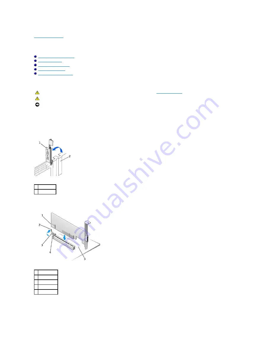
Remove the filler bracket by raising the hinged lever and sliding the filler bracket up.  
 

Removing the Filler Bracket  


Installing the DVI Adapter  


4.


Press the card-clip lever toward the PCI card slot and gently press the card into the PCI Express x16 slot until it clicks into place.  


5.


Release the card-clip lever, ensuring that the tab on the card-clip lever fits into the notch on the front end of the card.  


6.


Secure the card by lowering the hinged lever on the back panel.  


CAUTION: 

Before you begin any of the procedures in this section, follow the steps in "

Safety Instructions

."


CAUTION: 

To guard against electrical shock, always unplug your computer from the electrical outlet before opening the cover.

NOTICE: 

To disconnect a network cable, first unplug the cable from your computer, and then unplug it from the network wall jack. 

1

hinged lever

2

filler bracket

1

card notch

2

card-clip lever

3

card-clip tab

4

card clip

5

PCI card slot

Содержание GX280DT - GX280 Desktop Computer

Страница 1: ...ument is subject to change without notice 2004 Dell Inc All rights reserved Reproduction in any manner whatsoever without the written permission of Dell Inc is strictly forbidden Trademarks used in this text Dell and the DELL logo are trademarks of Dell Inc Microsoft Windows and Windows NT are registered trademarks of Microsoft Corporation Intel is a registered trademark of Intel Corporation Other...

Страница 2: ...nd gently press the card into the PCI Express x16 slot until it clicks into place 5 Release the card clip lever ensuring that the tab on the card clip lever fits into the notch on the front end of the card 6 Secure the card by lowering the hinged lever on the back panel CAUTION Before you begin any of the procedures in this section follow the steps in Safety Instructions CAUTION To guard against e...

Страница 3: ...ny cables that will not reach the card cage once they are removed from the computer b Gently rotate and pull on the handle to lift the card cage away from the computer Removing the Card Cage 3 Remove the filler bracket to create an empty card slot opening in the card cage a Press the release tab at the top of the card cage b Rotate the card retention lever upward to unlock and lift the filler brac...

Страница 4: ...e that the riser boards are fully seated in the connectors on the system board Replacing the Card Cage 1 release tab 2 card retention lever 3 card slot NOTE See the documentation that came with the card for information on configuring the card making internal connections or customizing it for your computer CAUTION Some network adapters automatically start the computer when you connect them to a net...

Страница 5: ...tab on the card clip lever fits into the notch on the front end of the card b Secure the card by lowering the hinged lever on the back panel Inserting the Card 1 card cage 2 slots 3 riser boards 2 4 system board connectors 2 NOTICE Do not route card cables over or behind the cards Cables routed over the cards can prevent the computer cover from closing properly or cause damage to the equipment NOT...

Страница 6: ...inue holding the lever and pull the lever up Removing the Filler Bracket 1 DVI card 2 card retention lever 3 securing slot not on all cards 4 securing tab 5 card connector NOTICE To connect a network cable first plug the cable into the network wall jack and then plug it into the computer CAUTION Before you begin any of the procedures in this section follow the steps in Safety Instructions CAUTION ...

Страница 7: ... on Mini Tower Computer 1 Open the computer cover 2 Remove the filler bracket by raising the hinged lever and sliding the bracket up Installing the DVI Adapter 1 hinged lever 2 indented tab side view 1 card notch 2 card clip lever 3 card clip tab 4 card clip 5 PCI card slot NOTICE To connect a network cable first plug the cable into the network wall jack and then plug it into the computer CAUTION ...

Страница 8: ...mputer cover 2 Remove the filler bracket by raising the hinged lever and sliding the bracket up Removing the Filler Bracket Installing the DVI Adapter 2 card clip lever 3 card clip tab 4 card clip NOTICE To connect a network cable first plug the cable into the network wall jack and then plug it into the computer CAUTION Before you begin any of the procedures in this section follow the steps in Saf...

Страница 9: ... the front end of the card 5 Secure the card by lowering the hinged lever on the back panel 6 Close the computer cover 7 Connect the monitor cable to the card s video connector 8 Connect your computer and devices to electrical outlets and turn them on Back to Contents Page 3 card clip tab 4 card clip 5 PCI card slot NOTICE To connect a network cable first plug the cable into the network wall jack ...

Страница 10: ...asures l Reorient or relocate the receiving antenna l Increase the separation between the equipment and the receiver l Connect the equipment into an outlet on a circuit different from that to which the receiver is connected l Consult the dealer or an experienced radio television technician for help IC Notice Canada Only Most Dell computer systems and other Dell digital apparatus are classified by ...

Страница 11: ...BSMI Notice Taiwan Only If you find a or mark on the regulatory label on the bottom side or back panel of your computer the following section is applicable Back to Contents Page ...

Страница 12: ... metal mounting bracket Hold a component such as a microprocessor chip by its edges not by its pins Protecting Against Electrostatic Discharge Static electricity can harm delicate components inside your computer To prevent static damage discharge static electricity from your body before you touch any of your computer s electronic components such as the microprocessor You can do so by touching an u...

Страница 13: ...tion Dimensions Back to Contents Page Computer DVI digital only connector Bus type Intel Digital Video Output DVO Maximum resolution supported 1600 x 1200 at 60 Hz Power requirements Max Power 12 V 1135 mW 3 3 V 728 mW Bracket height low profile 7 92 cm 3 118 in standard 10 67 cm 4 725 in Board dimensions low profile and standard 14 48 cm 5 7 in long by 6 93 cm 2 73 in high ...

Страница 14: ...t 3 Attach a CRT monitor to the VGA connection to ensure that the system is producing a video signal using the integrated controller 4 If the monitor is capable of both VGA and DVI input ensure that the input selector on the monitor is set correctly 5 If the card is not properly detected reseat the DVI card in the PCI Express x16 slot to ensure a good connection See the Installation Instructions 6...

Отзывы: