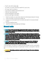
NOTE:
Coat the one-hole lug with an anti-oxidant compound before crimping. Also,
bring any unplated mating surfaces to a shiny finish and coat with an anti-oxidant
before mating. Plated mating surfaces must be clean and free from contamination.
NOTE:
The rack installation ears are not suitable for grounding.
Before you install the switch into the dual-tray:
1
Cut the ground cable (not included) to the desired length. The cable length must
facilitate proper operation of the fault interrupt circuits. Use the shortest cable route
allowable.
2
Unscrew the two attached M4 screws and set aside.
3
Attach the ground lug and bracket to the switch using the M4 screws.
4
Using one of the two M4 threaded holes, attach the ground cable to the lug. Use the
M4 screw with a captive internal tooth lock washer. Torque the screw to ±5-6 in-lbs.
5
Attach the other end of the ground cable to a suitable ground point such as the rack or
cabinet.
The rack installation ears are not a suitable grounding point.
Rack or cabinet installation
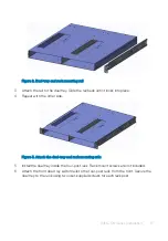
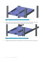
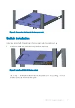
You may either place the switch on a rack shelf or mount the switch directly into a 19" wide,
EIA-310- E-compliant rack. The dual-tray mounting rails ship with the dual tray, not the
switch.
WARNING:
This guide is a condensed reference. Read the safety instructions in
your
Safety, Environmental, and Regulatory
information booklet before you begin.
NOTE:
The illustrations in this section are not intended to represent a specific
switch.
NOTE:
Do not the use the mounted rails as a shelf or a workplace.
Rack mount safety considerations
•
Rack loading—Overloading or uneven loading of racks may result in shelf or rack failure,
possibly damaging the equipment and causing personal injury. Stabilize racks in a
permanent location before loading begins. Mount the components starting at the
bottom of the rack, then work to the top. Do not exceed your rack’s load rating.
•
Power considerations—Connect only to the power source specified on the unit. When
you install multiple electrical components in a rack, ensure that the total component
S4112-ON Series Installation
13
Содержание EMC S4112-ON Series
Страница 1: ...S4112 ON Series Setup Guide ...
Страница 4: ...Chassis physical design 23 5 Support 26 4 Contents ...


