Replacing the system board
WARNING: Before working inside your Embedded Box PC, read the safety
information that shipped with your Embedded Box PC and follow the steps
in
Before working inside your Embedded Box PC
. After working inside your
Embedded Box PC, follow the steps in
After working inside your Embedded
. For more safety best practices, see the Regulatory Compliance
home page at
www.dell.com/regulatory_compliance
NOTE: Your Embedded Box PC’s Service Tag is stored in the system board.
You must enter the Service Tag in the BIOS setup program after you replace
the system board.
NOTE: Replacing the system board removes any changes you have made to
the BIOS using the BIOS setup program. You must make the appropriate
changes again after you replace the system board.
Procedure
1
Place the system board on the chassis.
2
Align the screw holes on the system board with the screw holes in the chassis.
3
Replace the screws that secure the system board to the chassis.
4
Connect the serial-port cable, SATA data-cable, and SATA power-cable to the
connectors on the system board.
Post-requisites
1
Replace the
2
Follow step 2 to step 6 in
3
Replace the
4
Replace the
5
Replace the
6
Replace the
.
7
Replace the
.
8
Replace the
.
9
Replace the
or
123
Содержание Embedded Box PC5000
Страница 22: ...6 Lift the back cover off the chassis 1 back cover 2 chassis 7 Remove the Removing the hard drive cage 22 ...
Страница 25: ...2 Lift the hard drive cage from the back cover 1 hard drive cage 2 M3x5 screws 4 3 back cover 25 ...
Страница 45: ...4 Remove the filler plate from the chassis 1 M3x5 countersunk screw 2 bracket 3 filler plate 4 chassis 45 ...
Страница 57: ...5 Remove the WLAN antenna cable off the chassis 1 antenna cables 2 routing guide 3 WLAN card 57 ...
Страница 66: ...5 Remove the WLAN antenna cable off the chassis 1 WWAN antenna cables 2 2 routing guide 3 WWAN card 66 ...
Страница 74: ...3 Remove the SIM card from the SIM card slot 1 SIM card slot lock 2 SIM card slot 3 SIM card 74 ...
Страница 85: ...2 Lift the coin cell battery out of its socket 1 plastic scribe 2 battery release lever 3 coin cell battery 85 ...
Страница 95: ...2 Remove the top cover off the chassis 1 M3x5 countersunk screws 7 2 bottom cover 3 chassis 95 ...
Страница 99: ...4 Remove the riser card bracket from the riser card 1 riser card bracket 2 screws 2 3 riser card 99 ...
Страница 111: ...4 Remove the top cover off the chassis 1 M3x5 countersunk screws 7 2 top cover 3 chassis 5 Remove the power switch 111 ...
Страница 117: ...2 Lift the CPU board off the system board 1 M2 5x6 screws 2 2 STDF L5 HEX M2 5x4 screws 3 3 CPU board 117 ...
Страница 122: ...3 Lift the system board off the chassis 1 chassis 2 system board 122 ...
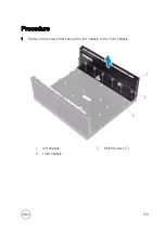
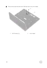
Страница 130: ...2 Remove the screws that secure the Dell logo board to the front chassis 1 M3x5 screws 3 2 front chassis 130 ...
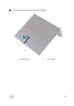
Страница 131: ...3 Remove the Dell logo board from the front chassis 1 Dell logo board 2 front chassis 131 ...
Страница 133: ...15 Follow step 2 to step 8 in Replacing the back cover 133 ...
Страница 136: ...CANbus The CANBus daughter card is an optional accessory for Embedded Box PC 136 ...


