Dell E173FPc
11
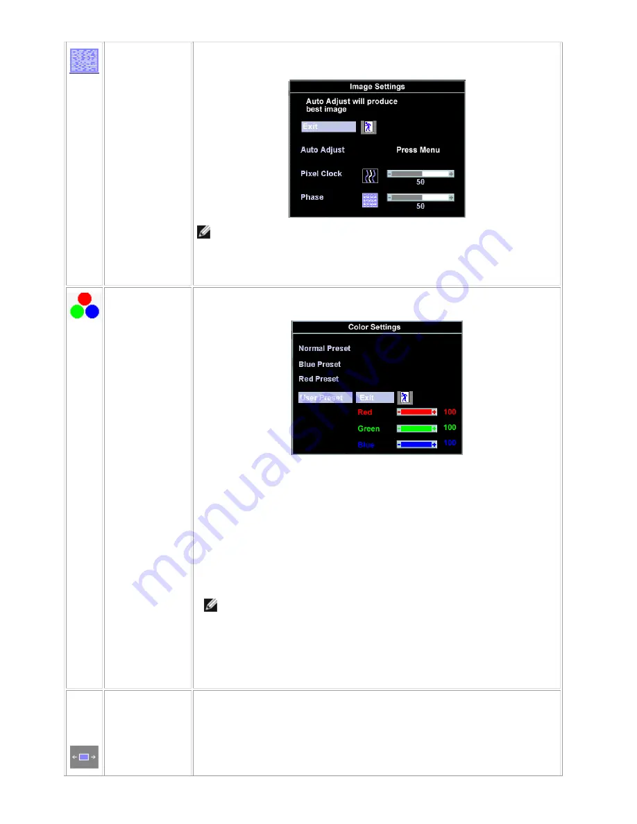
Phase
If satisfactory results are not obtained using the 'Phase' adjustment, use the 'Pixel
Clock' adjustment and then use 'Phase' again.
NOTE: This function may change the width of the display image. Use the
'
Horizontal
'
function of the
'
Position
'
menu to center the display image on the
screen.
Color Settings:
'Color Settings' adjusts the color temperature and saturation.
Normal Preset
'Normal Preset' is selected to obtain the default (factory) color settings.
Blue Preset
'Blue Preset' is selected to obtain a bluish tint. This color setting is typically used for
text based applications (Spreadsheets, Programming, Text Editors etc.).
Red Preset
'Red Preset' is selected to obtain a redder tint. This color setting is typically used for
color intensive applications (Photograph Image Editing, Multimedia, Movies etc.).
User Preset
'User Preset': Use the plus and minus buttons to increase or decrease each of the
three colors (R, G, B) independently, in single digit increments, from '0' to '100'.
NOTE:
'
Color temperature
'
is a measure of the 'warmth' of the image colors
(red/green/blue). The two available presets ('Blue' and 'Red') favor blue and
red accordingly. Select each one to see how each range suits your eye; or
utilize the 'User Preset' option to customize the color settings to your exact
choice.
OSD Settings:
Each time the OSD opens, it displays in the same location on the screen. 'OSD
Settings' (horizontal/vertical) provides control over this location.
Horizontal
Position
-
and + buttons move OSD to the left and right.
Содержание E173FPc
Страница 16: ...Dell E173FPc 16 4 4 Panel Specification 4 4 1 Display Characteristics For LPL panel For Hydis panel ...
Страница 17: ...Dell E173FPc 17 Display Characteristics For CPT panel ...
Страница 19: ...Dell E173FPc 19 For Hydis panel ...
Страница 20: ...Dell E173FPc 20 For CPT panel ...
Страница 21: ...Dell E173FPc 21 5 Block Diagram 5 1 Exploded View ...
Страница 24: ...Dell E173FPc 24 5 3 Electrical Block Diagram 5 3 1 Main Board ...
Страница 30: ...Dell E173FPc 30 The end The angle between CCFL line and vertical direction should be 30 40 degree ...
Страница 36: ...Dell E173FPc 36 7 2 PWPC Board ...
Страница 37: ...Dell E173FPc 37 ...
Страница 38: ...Dell E173FPc 38 8 PCB Layout 8 1 Main Board ...
Страница 39: ...Dell E173FPc 39 ...
Страница 40: ...Dell E173FPc 40 ...
Страница 41: ...Dell E173FPc 41 8 2 PWPC Board ...
Страница 42: ...Dell E173FPc 42 ...
Страница 43: ...Dell E173FPc 43 ...
Страница 53: ...Dell E173FPc 53 b Click the Select Chip button and choose the type you are going to program ...
Страница 54: ...Dell E173FPc 54 c Click the Select Bank0 button and selecting a file which a binary Format required ...
Страница 55: ...Dell E173FPc 55 d Select the communication Setting Port Name e Click the ConNect button ...
Страница 70: ...Dell E173FPc 70 15 2 HT17E13 100 ...
Страница 71: ...Dell E173FPc 71 15 3 CLAA170EA 07 ...
Страница 72: ...Dell E173FPc 72 ...


