Touch Pad:
1
touch pad cable
D1690
2
system-board ZIF connector
Back to Contents Page
file:///I|/SERVICE%20MANUALS/DELL%20MANUALS/LA...Latitude/D400/D400_SERVICE_MANUAL/touchpad.htm (4 of 4)6/21/2004 1:56:14 AM
Страница 1: ...Thank you for purchasing this Factory Service Manual CD DVD from servicemanuals4u com Please check out our eBay auctions for more great deals on Factory Service Manuals servicemanuals4u ...
Страница 2: ...emory Module Under the Memory Module Modem Cover Installing a Memory Module Under the Keyboard Mini PCI Card Modem Hard Drive Removing the Hard Drive Installing the Hard Drive Removing the Interposer Replacing the Interposer Docking Doors Removing the Docking Doors Installing the Docking Doors Bluetooth Display Removing the Display Assembly Replacing the Display Latch Palm Rest Cooling Fan Touch P...
Страница 3: ...hout notice 2003 Dell Inc All rights reserved Reproduction in any manner whatsoever without the written permission of Dell Inc is strictly forbidden Trademarks used in this text Dell the DELL logo and Latitude are trademarks of Dell Inc Microsoft and Windows are registered trademarks of Microsoft Corporation Bluetooth is a trademark owned by Bluetooth SIG Inc and is used by Dell Inc under license ...
Страница 4: ...CAUTION Handle components and cards with care Do not touch the components or contacts on a card Hold a card by its edges or by its metal mounting bracket Hold a component such as a microprocessor by its edges not by its pins NOTICE To avoid damaging the computer perform the following steps before you begin working inside the computer 1 Ensure that the work surface is flat and clean to prevent scra...
Страница 5: ...d turn the computer upside down on a flat work surface NOTICE To avoid damaging the system board you must remove the main battery before you service the computer 10 Slide and hold the battery bay latch release on the bottom of the computer and then remove the battery from the bay Recommended Tools The procedures in this manual require the following tools Phillips screwdriver file I SERVICE 20MANUA...
Страница 6: ...at blade screwdriver Small plastic scribe Flash BIOS update program floppy disk or CD Computer Orientation 1 back 2 right 3 front 4 left file I SERVICE 20MANUALS DELL 20MANUALS LA ok Latitude D400 D400_SERVICE_MANUAL begin htm 3 of 6 6 21 2004 1 56 01 AM ...
Страница 7: ...ep track of the screws The screw identification chart provides the number of screws and their sizes keyboard two each 1428U modem one each 1428U hard drive four each 2864D display removal six each 4911U display bezel six each 7166P display latch two each 5H953 file I SERVICE 20MANUALS DELL 20MANUALS LA ok Latitude D400 D400_SERVICE_MANUAL begin htm 4 of 6 6 21 2004 1 56 01 AM ...
Страница 8: ... 4911U two each 5H953 fan three each 1428U system board six each 1428U one each if a BIOS card is present 1428U speakers two each 4911U Back to Contents Page file I SERVICE 20MANUALS DELL 20MANUALS LA ok Latitude D400 D400_SERVICE_MANUAL begin htm 5 of 6 6 21 2004 1 56 01 AM ...
Страница 9: ...Before You Begin Dell Latitude D400 Service Manual file I SERVICE 20MANUALS DELL 20MANUALS LA ok Latitude D400 D400_SERVICE_MANUAL begin htm 6 of 6 6 21 2004 1 56 01 AM ...
Страница 10: ...ell Diagnostics Features of the Dell Diagnostics The Dell Diagnostics helps you to check your computer hardware without any additional equipment and without destroying any data By using the diagnostics you can have confidence in the operation of your computer If you find a problem that you cannot solve by yourself the diagnostic tests can provide you with important information you need when talkin...
Страница 11: ...cs You do not need to highlight Diagnostics and press Enter The computer automatically runs the Pre boot System Assessment 4 Turn on the computer When the DELL logo appears press F12 immediately If you wait too long and the Microsoft Windows logo appears continue to wait until you see the Windows desktop Then shut down your computer and try again 5 When the boot device list appears highlight Diagn...
Страница 12: ...rough check of devices The test typically takes 1 hour or more and requires you to answer questions periodically Custom Test Tests a specific device You can customize the tests to be run Symptom Tree Allows you to select tests based on a symptom of the problem you are experiencing The option lists the most common symptoms 8 If a problem is encountered during a test a message appears displaying the...
Страница 13: ...mation on the system setup program The device list may not display the names of all the components installed on your computer or all devices attached to your computer Parameters Allows you to customize the test by changing the test settings 10 When you have finished running a test close the screen to return to the Main Menu screen To exit the Dell Diagnostics and reboot the computer close the Main...
Страница 14: ... due to servicing that is not authorized by Dell is not covered by your warranty NOTICE Unless otherwise noted each procedure in this document assumes that a part can be replaced by performing the removal procedure in reverse order file I SERVICE 20MANUALS DELL 20MANUALS LA k Latitude D400 D400_SERVICE_MANUAL system htm 1 of 2 6 21 2004 1 56 03 AM ...
Страница 15: ...ery See Mini RSL 5 DIMM1 cover 2X386 14 computer base D2389 6 metal shield 2X370 15 reserve battery 3U490 7 Hard drive controller card 2X372 16 display connector 2X241 8 system board See Mini RSL 17 center control cover 5U447 9 fan 6U568 Back to Contents Page file I SERVICE 20MANUALS DELL 20MANUALS LA k Latitude D400 D400_SERVICE_MANUAL system htm 2 of 2 6 21 2004 1 56 03 AM ...
Страница 16: ... metal surface such as the back panel on the computer 1 Follow the instructions in Preparing to Work Inside the Computer to remove the battery and prepare the computer for work 2 Open the display approximately 180 degrees 3 Use a plastic scribe or if a plastic scribe is not available carefully use a small flat blade screwdriver to lift the notched right edge of the center control cover and pry the...
Страница 17: ...o M2 x 5 mm screws from the top of the keyboard 5 Use the pull tab to pull the keyboard up and out toward the display of the bottom case file I SERVICE 20MANUALS DELL 20MANUALS LA Latitude D400 D400_SERVICE_MANUAL keyboard htm 2 of 5 6 21 2004 1 56 04 AM ...
Страница 18: ...yboard face down on the palm rest 7 Pull straight up on the pull tab that is attached to the keyboard connector to disconnect the connector from the interface connector on the system board file I SERVICE 20MANUALS DELL 20MANUALS LA Latitude D400 D400_SERVICE_MANUAL keyboard htm 3 of 5 6 21 2004 1 56 04 AM ...
Страница 19: ... on the keyboard into their respective slots in the palm rest 3 Replace the two screws at the top of the keyboard 4 Replace the center control cover and snap it down starting on the left side and working to the right side so that it is flush with the palm rest Back to Contents Page file I SERVICE 20MANUALS DELL 20MANUALS LA Latitude D400 D400_SERVICE_MANUAL keyboard htm 4 of 5 6 21 2004 1 56 04 AM...
Страница 20: ...Keyboard file I SERVICE 20MANUALS DELL 20MANUALS LA Latitude D400 D400_SERVICE_MANUAL keyboard htm 5 of 5 6 21 2004 1 56 04 AM ...
Страница 21: ...ace such as the back panel on the computer 1 Follow the instructions in Preparing to Work Inside the Computer to remove the battery and prepare the computer for work 2 Continue to the appropriate section Installing a Memory Module Under the Memory Module Modem Cover Installing a Memory Module Under the Keyboard Installing a Memory Module Under the Memory Module Modem Cover 1 Turn the computer over...
Страница 22: ...uring clips 2 If you are replacing a memory module remove the existing module a Use your fingertips to carefully spread apart the securing clips on each end of the memory module connector until the module pops up b Remove the module from the connector file I SERVICE 20MANUALS DELL 20MANUALS L Latitude D400 D400_SERVICE_MANUAL memory htm 2 of 6 6 21 2004 1 56 06 AM ...
Страница 23: ...ule firmly into the slot at a 45 degree angle and rotate the module down until it clicks into place If you do not feel the click remove the module and reinstall it NOTE If the memory module is not installed properly the computer may not boot properly No error message indicates this failure file I SERVICE 20MANUALS DELL 20MANUALS L Latitude D400 D400_SERVICE_MANUAL memory htm 3 of 6 6 21 2004 1 56 ...
Страница 24: ...he additional memory and automatically updates the system configuration information To confirm the amount of memory installed in the computer In the Microsoft Windows XP operating system click the Start button click Help and Support and then click Computer Information In Windows 2000 right click the My Computer icon on your desktop and then click the General tab Installing a Memory Module Under th...
Страница 25: ...ee Mini RSL 4 securing clips 2 5 securing tabs 3 NOTICE To prevent damage to the memory module connector do not use tools to spread the memory module securing clips 3 If you are replacing a memory module remove the existing module file I SERVICE 20MANUALS DELL 20MANUALS L Latitude D400 D400_SERVICE_MANUAL memory htm 5 of 6 6 21 2004 1 56 06 AM ...
Страница 26: ...connector and tighten the captive screws NOTICE If the DIMM1 cover is difficult to replace remove the module and reinstall it Forcing the cover to close may damage your computer 6 Replace the keyboard 7 Insert the battery into the battery bay or connect the AC adapter to your computer and an electrical outlet 8 Turn on the computer As the computer boots it detects the additional memory and automat...
Страница 27: ...d metal surface such as the back panel on the computer 1 Follow the instructions in Preparing to Work Inside the Computer to remove the battery and prepare the computer for work 2 Remove the keyboard 3 If a Mini PCI card is not already installed go to step 4 If you are replacing a Mini PCI card remove the existing card a Disconnect the Mini PCI card from the attached cables file I SERVICE 20MANUAL...
Страница 28: ...0846 b Release the Mini PCI card by spreading the metal securing tabs until the card pops up slightly c Lift the Mini PCI card out of its connector file I SERVICE 20MANUALS DELL 20MANUALS LA Latitude D400 D400_SERVICE_MANUAL minipci htm 2 of 4 6 21 2004 1 56 06 AM ...
Страница 29: ... care because they are very fragile NOTE If a Mini PCI card was not already installed remove the foam that secures the antenna cables before you install the card 4 Align the Mini PCI card with the connector at a 45 degree angle and press the Mini PCI card into the connector until you feel a click 5 Connect the antenna cables to the Mini PCI card with the white cable in the Mini PCI connector file ...
Страница 30: ...st and the black cable in the Mini PCI card connector closer to the display 6 Replace the keyboard Back to Contents Page file I SERVICE 20MANUALS DELL 20MANUALS LA Latitude D400 D400_SERVICE_MANUAL minipci htm 4 of 4 6 21 2004 1 56 06 AM ...
Страница 31: ...tions in Preparing to Work Inside the Computer to remove the battery and prepare the computer for work NOTICE Handle components and cards by their edges and avoid touching pins and contacts Ground yourself by touching a metal connector on the back of the computer Continue to ground yourself periodically during this procedure 2 Turn the computer over loosen the captive screws on the memory module m...
Страница 32: ...f its connector on the system board and disconnect the modem cable 4 Connect the modem cable to the modem NOTICE The cable connectors are keyed for correct insertion do not force the connections 5 Align the modem with the screw hole and press the modem into the connector on the system board 6 Install the screw to secure the modem to the system board 7 Replace the modem cover Back to Contents Page ...
Страница 33: ...uter before removing the hard drive Do not remove the hard drive while the computer is on in standby mode or in hibernate mode NOTICE Hard drives are extremely fragile even a slight bump can damage the drive NOTE Dell does not guarantee compatibility or provide support for hard drives from sources other than Dell To remove the hard drive in the hard drive bay 1 Follow the instructions in Preparing...
Страница 34: ...shipping the hard drive 2 Slide the hard drive into the bay until it is fully seated 3 Replace and tighten the two M3 x 3 mm screws 4 Use the Operating System CD to install the operating system for your computer 5 Use the Drivers and Utilities CD to install the drivers and utilities for your computer file I SERVICE 20MANUALS DELL 20MANUALS LA 20ok Latitude D400 D400_SERVICE_MANUAL hdd htm 2 of 5 6...
Страница 35: ...ve the hard drive 3 Remove the two M3 x 3 mm screws from the side of the hard drive and remove the hard drive carrier 1 M3 x 3 mm screws 2 2864D 2 hard drive carrier 7X499 4 Carefully remove the interposer by pulling it straight off the hard drive file I SERVICE 20MANUALS DELL 20MANUALS LA 20ok Latitude D400 D400_SERVICE_MANUAL hdd htm 3 of 5 6 21 2004 1 56 08 AM ...
Страница 36: ...arrier to the new hard drive and replace the two M3 x 3 mm screws 2 Carefully attach the interposer from the old hard drive by pushing it straight onto the hard drive Ensure that the pins are oriented correctly When the interposer is attached correctly four extra pins are on one side file I SERVICE 20MANUALS DELL 20MANUALS LA 20ok Latitude D400 D400_SERVICE_MANUAL hdd htm 4 of 5 6 21 2004 1 56 08 ...
Страница 37: ...Hard Drive 1 interposer 8267R 3 Install the hard drive Back to Contents Page file I SERVICE 20MANUALS DELL 20MANUALS LA 20ok Latitude D400 D400_SERVICE_MANUAL hdd htm 5 of 5 6 21 2004 1 56 08 AM ...
Страница 38: ...atic discharge ground yourself by using a wrist grounding strap or by periodically touching an unpainted metal surface such as the back panel on the computer 1 Follow the instructions in Preparing to Work Inside the Computer to remove the battery and prepare the computer for work 2 Gently bend the docking doors and lift them away from the computer base file I SERVICE 20MANUALS DELL 20MANUALS LA La...
Страница 39: ...rs 8X516 Installing the Docking Doors Slide the side of the docking doors with the spring over the longer posts file I SERVICE 20MANUALS DELL 20MANUALS LA Latitude D400 D400_SERVICE_MANUAL dockdoor htm 2 of 3 6 21 2004 1 56 09 AM ...
Страница 40: ...Docking Doors 1 docking doors with spring 8X516 2 longer post Back to Contents Page file I SERVICE 20MANUALS DELL 20MANUALS LA Latitude D400 D400_SERVICE_MANUAL dockdoor htm 3 of 3 6 21 2004 1 56 09 AM ...
Страница 41: ...ng an unpainted metal surface such as the back panel on the computer 1 Follow the instructions in Preparing to Work Inside the Computer to remove the battery and prepare the computer for work 2 Turn the computer over loosen the captive screw in the Bluetooth module cover and remove the cover 1 Bluetooth module cover 0X737 2 captive screw 3 battery bay file I SERVICE 20MANUALS DELL 20MANUALS LA 0ok...
Страница 42: ...th module front 2U381 4 Ensure that the front of the Bluetooth module silver is facing outward and connect the cable to the module 5 Insert the module into the slot 6 Replace the cover and tighten the captive screw Back to Contents Page file I SERVICE 20MANUALS DELL 20MANUALS LA 0ok Latitude D400 D400_SERVICE_MANUAL blue htm 2 of 2 6 21 2004 1 56 10 AM ...
Страница 43: ... using a wrist grounding strap or by periodically touching an unpainted metal surface such as the back panel on the computer 1 Follow the instructions in Preparing to Work Inside the Computer to remove the battery and prepare the computer for work 2 Remove the battery 3 Remove the hard drive 4 Remove the center control cover 5 Remove the two M2 5 x 6 mm screws next to each hinge file I SERVICE 20M...
Страница 44: ...isplay assembly to an upright position and pull it up out of the computer Replacing the Display Latch CAUTION Before performing the following procedures read the safety instructions in your System Information Guide NOTICE To avoid electrostatic discharge ground yourself by using a wrist grounding strap or by periodically touching an unpainted metal surface such as the back panel on the computer fi...
Страница 45: ... screw bumpers and the six M2 5 x 4 mm screws that secure the bezel 1 rubber screw bumpers 6U549 2 bezel 3 rubber screw covers 2U940 4 M2 5 x 4 mm screws 7116P 5 Use your fingers to carefully pry around the perimeter of the bezel until the bezel separates from the display assembly 6 Remove the two display latch screws and remove the display latch file I SERVICE 20MANUALS DELL 20MANUALS LA Latitude...
Страница 46: ...2 display latch NOTICE When you replace the bezel ensure that the display cable is routed correctly Back to Contents Page file I SERVICE 20MANUALS DELL 20MANUALS LA Latitude D400 D400_SERVICE_MANUAL display htm 4 of 4 6 21 2004 1 56 11 AM ...
Страница 47: ... on the computer 1 Follow the instructions in Preparing to Work Inside the Computer to remove the battery and prepare the computer for work 2 Remove the hard drive 3 Remove the keyboard NOTICE You must remove the display assembly before you remove the palm rest the display hinges pass through the back of the palm rest 4 Remove the display 5 Turn the computer over and remove the nine M2 5 x 6 mm sc...
Страница 48: ...ws 9 4911U 6 Remove the two M2 x 1 8 mm screws located inside the battery bay 7 Turn the computer over and remove the four M2 5 x 6 mm screws file I SERVICE 20MANUALS DELL 20MANUALS LA Latitude D400 D400_SERVICE_MANUAL palmrest htm 2 of 5 6 21 2004 1 56 12 AM ...
Страница 49: ... 1 M2 5 x 6 mm screws 4 4911U 8 Disconnect the speaker connector and remove the speaker cable file I SERVICE 20MANUALS DELL 20MANUALS LA Latitude D400 D400_SERVICE_MANUAL palmrest htm 3 of 5 6 21 2004 1 56 12 AM ...
Страница 50: ...Pull up on the palm rest connector tab and disconnect the ZIF connector from the system board 10 Disengage the four battery bay tabs file I SERVICE 20MANUALS DELL 20MANUALS LA Latitude D400 D400_SERVICE_MANUAL palmrest htm 4 of 5 6 21 2004 1 56 12 AM ...
Страница 51: ...Palm Rest 11 Lift the palm rest away Back to Contents Page file I SERVICE 20MANUALS DELL 20MANUALS LA Latitude D400 D400_SERVICE_MANUAL palmrest htm 5 of 5 6 21 2004 1 56 12 AM ...
Страница 52: ... the back panel on the computer 1 Follow the instructions in Preparing to Work Inside the Computer to remove the battery and prepare the computer for work 2 Remove any installed memory modules smart card modem or PC Card 3 Remove the hard drive 4 Remove the keyboard 5 Remove the display 6 Remove the palm rest 7 Remove the fan cable from the fan extender cable that runs under the system board file ...
Страница 53: ...ws 3 1428U 8 Remove the three M2 x 5 mm screws that secure the cooling fan 9 Lift out the cooling fan Back to Contents Page file I SERVICE 20MANUALS DELL 20MANUALS LA 20ok Latitude D400 D400_SERVICE_MANUAL fan htm 2 of 2 6 21 2004 1 56 13 AM ...
Страница 54: ...surface such as the back panel on the computer 1 Follow the instructions in Preparing to Work Inside the Computer to remove the battery and prepare the computer for work 2 Remove any installed memory modules smart card modem or PC Card 3 Remove the hard drive 4 Remove the keyboard 5 Remove the display 6 Remove the palm rest 7 Gently lift up the touch pad using the pull tab file I SERVICE 20MANUALS...
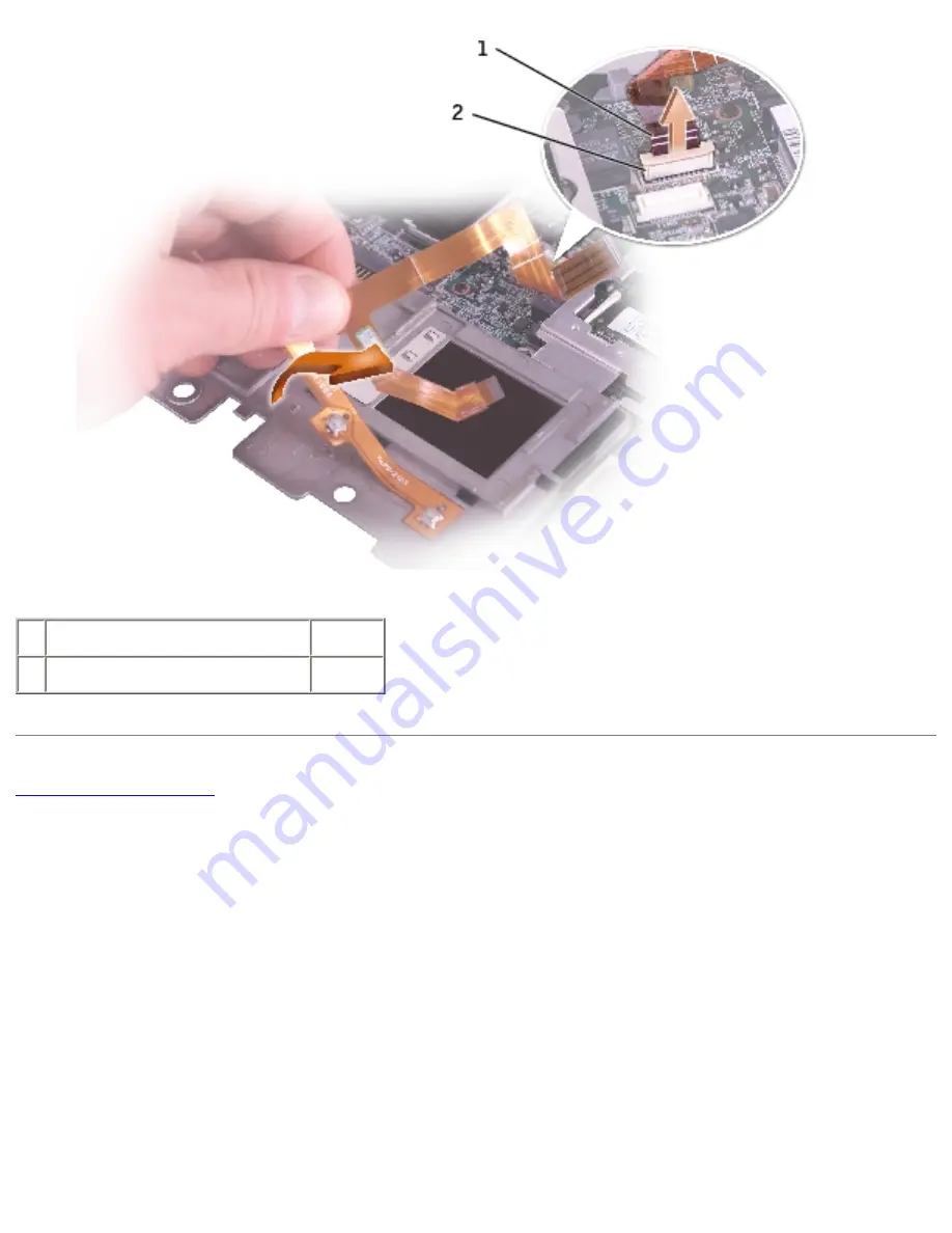
Страница 55: ...h pad D1690 2 pull tab 8 Very carefully remove the touch pad cable from the touch pad ZIF connector file I SERVICE 20MANUALS DELL 20MANUALS LA Latitude D400 D400_SERVICE_MANUAL touchpad htm 2 of 4 6 21 2004 1 56 14 AM ...
Страница 56: ...e detaching or attaching it to the touch pad ZIF connector remove the touch pad cable from the system board ZIF connector and repeat the procedure using a new touch pad cable file I SERVICE 20MANUALS DELL 20MANUALS LA Latitude D400 D400_SERVICE_MANUAL touchpad htm 3 of 4 6 21 2004 1 56 14 AM ...
Страница 57: ...Touch Pad 1 touch pad cable D1690 2 system board ZIF connector Back to Contents Page file I SERVICE 20MANUALS DELL 20MANUALS LA Latitude D400 D400_SERVICE_MANUAL touchpad htm 4 of 4 6 21 2004 1 56 14 AM ...
Страница 58: ...n Guide NOTICE To avoid electrostatic discharge ground yourself by using a wrist grounding strap or by periodically touching an unpainted metal surface such as the back panel on the computer 1 Follow the instructions in Preparing to Work Inside the Computer to remove the battery and prepare the computer for work 2 Remove any installed memory modules smart card modem or PC Card 3 Remove the hard dr...
Страница 59: ...em Board 1 M2 x 5 mm screw 1428U 8 Disconnect the smart card cable from the system board file I SERVICE 20MANUALS DELL 20MANUALS LA Latitude D400 D400_SERVICE_MANUAL sysboard htm 2 of 7 6 21 2004 1 56 15 AM ...
Страница 60: ...e Bluetooth cable from the system board 1 Bluetooth cable 10 Remove the four M2 x 5 mm screws from the metal shield and remove the metal shield file I SERVICE 20MANUALS DELL 20MANUALS LA Latitude D400 D400_SERVICE_MANUAL sysboard htm 3 of 7 6 21 2004 1 56 15 AM ...
Страница 61: ... 5 mm screws 4 1428U 2 EMI shield 2X370 11 Remove the two M2 x 5 mm screws and remove the daughter card file I SERVICE 20MANUALS DELL 20MANUALS LA Latitude D400 D400_SERVICE_MANUAL sysboard htm 4 of 7 6 21 2004 1 56 15 AM ...
Страница 62: ...428U 2 Hard drive controller card 2X372 12 Disconnect the fan cable 13 Remove the system board from the computer base file I SERVICE 20MANUALS DELL 20MANUALS LA Latitude D400 D400_SERVICE_MANUAL sysboard htm 5 of 7 6 21 2004 1 56 15 AM ...
Страница 63: ...Board 1 system board See Mini RSL 2 computer base D2389 14 Remove the infrared sensor cover file I SERVICE 20MANUALS DELL 20MANUALS LA Latitude D400 D400_SERVICE_MANUAL sysboard htm 6 of 7 6 21 2004 1 56 15 AM ...
Страница 64: ...into the appropriate drive and turn on the computer Follow the instructions on the screen NOTE After replacing the system board be sure to enter the computer s Service Tag into the BIOS of the replacement system board Back to Contents Page file I SERVICE 20MANUALS DELL 20MANUALS LA Latitude D400 D400_SERVICE_MANUAL sysboard htm 7 of 7 6 21 2004 1 56 15 AM ...
Страница 65: ...tions in Preparing to Work Inside the Computer to remove the main battery and prepare the computer for work 2 Remove any installed memory modules smart card modem or PC Card 3 Remove the keyboard 4 Remove the display 5 Remove the palm rest NOTICE Note the reserve battery location before you remove it so that you can put the replacement reserve battery in the same location 6 Lift out the reserve ba...
Страница 66: ...eserve Battery 1 reserve battery 3U490 2 system board connector Back to Contents Page file I SERVICE 20MANUALS DELL 20MANUALS LA Latitude D400 D400_SERVICE_MANUAL reserve htm 2 of 2 6 21 2004 1 56 16 AM ...
Страница 67: ...t appear on the screen The computer continues to boot and updates the new BIOS When the flash update is complete the computer automatically reboots 3 Press F2 during POST to enter the system setup program 4 Press Alt and F to reset the computer defaults 5 Press Esc select Save changes and reboot and press Enter to save configuration changes 6 Remove the flash BIOS update program floppy disk or CD ...
Страница 68: ...ge ground yourself by using a wrist grounding strap or by periodically touching an unpainted metal surface such as the back panel on the computer Follow the instructions in the palm rest section The replacement palm rest contains the replacement speakers Back to Contents Page file I SERVICE 20MANUALS DELL 20MANUALS LAPTO ok Latitude D400 D400_SERVICE_MANUAL speakers htm6 21 2004 1 56 17 AM ...
Страница 69: ...tal surface such as the back panel on the computer 1 Follow the instructions in Preparing to Work Inside the Computer to remove the battery and prepare the computer for work 2 Remove any installed memory modules smart card modem or PC Card 3 Remove the keyboard 4 Remove the display 5 Remove the palm rest 6 Remove the system board 7 Press down on the battery latch to remove it file I SERVICE 20MANU...
Страница 70: ...ch 3 battery latch locking arm 8 Press in the spring and pull up on the battery latch locking arm Back to Contents Page file I SERVICE 20MANUALS DELL 20MANUALS LA ok Latitude D400 D400_SERVICE_MANUAL latch htm 2 of 2 6 21 2004 1 56 17 AM ...
Страница 71: ... for I O Connectors USB Connector Video Connector Serial Connector Dell D Bay Connector USB Connector Pin Signal 1 USB5V 2 USBP 3 USBP 4 GND Video Connector file I SERVICE 20MANUALS DELL 20MANUALS LA Latitude D400 D400_SERVICE_MANUAL pinouts htm 1 of 4 6 21 2004 1 56 18 AM ...
Страница 72: ...1 CRT_R 9 5V 2 CRT_G 10 GND 3 CRT_B 11 MONITOR_DETECT 4 NC 12 DDC_DATA 5 GND 13 CRT_HS 6 GND 14 CRT_VS 7 GND 15 DDC_CLK 8 GND Serial Connector file I SERVICE 20MANUALS DELL 20MANUALS LA Latitude D400 D400_SERVICE_MANUAL pinouts htm 2 of 4 6 21 2004 1 56 18 AM ...
Страница 73: ...A 8 CTS 4 DTR 9 RI 5 GND Dell D Bay Connector Pin Signal Pin Signal 1 USB_VCC 8 SMB_CLK 2 USB_D 9 GND 3 USB_D 10 SHIELD GND 4 USB_GND 11 SHIELD GND 5 PWR_SRC 12 SHIELD GND file I SERVICE 20MANUALS DELL 20MANUALS LA Latitude D400 D400_SERVICE_MANUAL pinouts htm 3 of 4 6 21 2004 1 56 18 AM ...
Страница 74: ...ments for I O Connectors 6 SMB_DAT 13 SHIELD GND 7 MODPRES 14 SHIELD GND Back to Contents Page file I SERVICE 20MANUALS DELL 20MANUALS LA Latitude D400 D400_SERVICE_MANUAL pinouts htm 4 of 4 6 21 2004 1 56 18 AM ...
Страница 75: ...uter base bottom plastics 2X386 DIMM1 cover 2X370 EMI shield D400 P0777 memory door with captive screws 4U465 rubber foot 3 0X737 Bluetooth module cover 8X516 docking doors or docking doors with spring P0777 memory module cover Base Bottom Plastics 2X370 metal shield 0X740 smart card reader CD ROM CD RW G0405 24X CD D module F0275 24X CD RW D module DVD ROM file I SERVICE 20MANUALS DELL 20MANUALS ...
Страница 76: ...40 G HDD D module second HDD HDD and D MOD housing 8267R interposer 2X372 hard drive controller card 8X217 60 G HDD 4P124 D MOD housing only no HDD 8267R HDD connector 2864D HDD mounting screws 2 2867R HDD security screws 2 7X499 primary HDD carrier with bezel Keyboard 5U447 center control cover P1290 keyboard or Keyboard Service Kit US LCD Display Assembly file I SERVICE 20MANUALS DELL 20MANUALS ...
Страница 77: ...M1400 802 11a b J0846 TM1300 802 11b g Modem 9X163 Modem Daughter Card Power Source 5U092 AC power brick only 65 W 9T215 AC power brick only 90 W must be used with D Dock and D Port F2952 duck head power supply plug direct to wall F2951 power cord US 0 9 m 3 ft K2596 power cord US 1 8 m 6 ft 8T016 primary battery 4 cell 14 8 V lithium 6T087 primary battery 6 cell 11 1 V lithium 3U490 reserve batte...
Страница 78: ...X1102 System Board Service Kit 1 7 GHz D400 Palm Rest Assembly 4U782 palm rest D1690 touch pad with cable 4U782 speaker Screws 5H953 M2 x 1 8 mm screw 1428U M2 x 5 mm screw 7116P M2 5 x 4 mm screw 4911U M2 5 x 6 mm screw 2864D M3 x 3 mm screw Back to Contents Page file I SERVICE 20MANUALS DELL 20MANUALS LA Latitude D400 D400_SERVICE_MANUAL minirsl htm 4 of 4 6 21 2004 1 56 19 AM ...