background image

30

Basic Operation

w

w

w

.d

el

l.

c

o

m

 |

 s

upp

ort

.del

l.

com

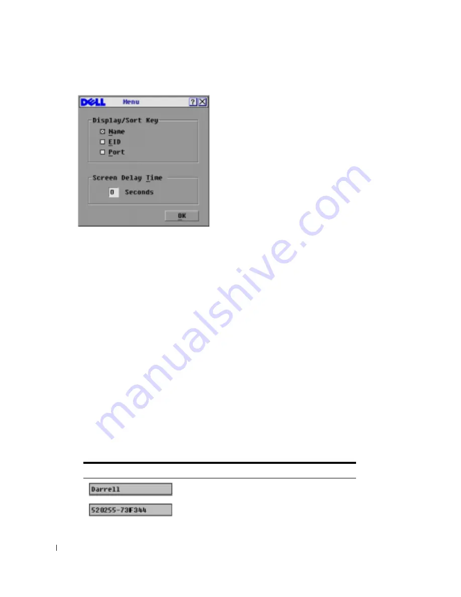
Figure 3-7. Menu Dialog Box

To choose the default display order of servers:

1

Select 

Name

 to display servers alphabetically by name.

-or-

Select 

EID

 to display servers numerically by EID number.

-or-

Select 

Port to display

 servers numerically by port number.

2

Click 

OK

.

To set a 

Screen Delay Time

 for the OSCAR interface:

1

Type in the number of seconds (0 to 9) to delay the OSCAR interface display after you press 

<Print Screen>. Entering <0> launches the OSCAR interface with no delay.

2

Click 

OK

.

Setting a 

Screen Delay Time

 allows you to complete a soft switch without the OSCAR interface 

displaying. To perform a soft switch, see "Soft Switching"

.

Controlling the Status Flag

The status flag displays on your desktop and shows the name or EID number of the selected server 

or the status of the selected port. Use the 

Flag

 dialog box to configure the flag to display by server 

name or EID number, or to change the flag color, opacity, display time and location on the desktop.

Table 3-4. OSCAR Status Flags

Flag

Description

Flag type by name

Flag type by EID number

Содержание Console Switch

Страница 1: ...w w w d e l l c o m s u p p o r t d e l l c o m Dell Console Switch Console Switch Installer User s Guide Model Console Switch ...

Страница 2: ... permission of Dell Inc is strictly forbidden Trademarks used in this text Dell and the DELL logo are trademarks of Dell Inc Avocent is a trademark of Avocent Corporation OSCAR is a registered trademark of Avocent Corporation or its affiliates Microsoft Windows and Windows NT are registered trademarks of Microsoft Corporation As an ENERGY STAR Partner Dell Inc has determined that this product meet...

Страница 3: ...ral 10 Rack Mounting of Systems 11 2 Installation Getting Started 13 Supplied with the Console Switch 13 Additional Items Needed 13 Rack Mounting Your Console Switch 13 Installing the Console Switch 14 Tiering Console Switches 16 Adding Legacy Switches 18 Setting Up Your Console Switch System 20 3 Basic Operation Controlling Your System at the Local User Ports 21 Viewing and Selecting Ports and Se...

Страница 4: ...P 36 Resetting Your Keyboard and Mouse 37 Scanning Your System 38 Running System Diagnostics 40 Broadcasting to Servers 42 Changing Your Switch Mode 16 port Console Switch Only 44 A Appendices Appendix A Flash Upgrades 47 Upgrading the Console Switch 47 Items Needed for the Upgrade 47 Upgrading Firmware 47 Upgrading the SIP 49 Appendix B Technical Specifications 52 Appendix C Notifications 54 USA ...

Страница 5: ...gure 3 3 Names Dialog Box 27 Figure 3 4 Name Modify Dialog Box 27 Figure 3 5 Devices Dialog Box 28 Figure 3 6 Device Modify Dialog Box 29 Figure 3 7 Menu Dialog Box 30 Figure 3 8 Flag Dialog Box 31 Figure 3 9 Set Position Flag 32 Figure 3 10 Security Dialog Box 33 Figure 3 11 Version Dialog Box 35 Figure 3 12 SIP Selection Dialog Box 36 Figure 3 13 SIP Version Dialog Box 36 Figure 3 14 SIP Version...

Страница 6: ...election Dialog Box 50 Figure 4 5 SIP Version Dialog Box 51 Figure 4 6 SIP Load Dialog Box 51 Tables Table 1 1 SIP Resolution and Refresh Rates 8 Table 2 1 Legacy Switch Support 18 Table 3 1 OSCAR Interface Status Symbols 22 Table 3 2 OSCAR Interface Navigation Basics 24 Table 3 3 Setup Features to Manage Routine Tasks for Your Servers 25 Table 3 4 OSCAR Status Flags 31 Table 3 5 Diagnostic Test D...

Страница 7: ...er Interface Pod SIP intelligent module By utilizing CAT 5 cabling the SIP dramatically reduces cable clutter while providing optimal resolution and video settings The built in memory of the SIP simplifies configuration by assigning and retaining unique server names and Electronic ID EID numbers for each attached server The SIP is powered directly from the server and provides Keep Alive functional...

Страница 8: ...system with a screen saver password After a user defined time the screen saver mode engages and access is prohibited until the appropriate password is entered to reactivate the system Video The Console Switch provides optimal resolution for analog VGA SVGA and XGA video Achieve resolutions of up to 1600 x 1200 with a 10 foot cable and up to 800 x 600 with a 100 foot cable Resolutions will vary dep...

Страница 9: ...ly scale to support more You can expand your system by tiering with Console Switches and legacy analog Console Switches This extra tier of units allows you to attach up to 256 servers in one system See Tiering Console Switches for more information Figure 1 2 Example of a Console Switch Configuration Safety Precautions Use the following safety guidelines to help ensure your own personal safety and ...

Страница 10: ...he product The product has been exposed to water The product has been dropped or damaged The product does not operate correctly when you follow the operating instructions Keep your system away from radiators and heat sources Also do not block cooling vents Do not spill food or liquids on your system components and never operate the product in a wet environment If the system gets wet see the approp...

Страница 11: ...anying the rack for specific caution statements and procedures System rack kits are intended to be installed in a rack by trained service technicians If a non Dell rack is utilized be sure that the rack meets the specifications of a Dell rack Elevated Ambient Temperature If installed in a closed rack assembly the operation temperature of the rack environment may be greater than room ambient Use ca...

Страница 12: ...12 Product Overview w w w d e l l c o m s u p p o r t d e l l c o m ...

Страница 13: ...ch Quick Installation Guide Additional Items Needed The following are additional items you may need to install your Console Switch One Server Interface Pod SIP module and UTP cabling per attached server or switch 1U mounting optional Rack Mounting Your Console Switch NOTE Rack mounting kits are sold separately Your Console Switch may be rack mounted using brackets available through Dell Before ins...

Страница 14: ...o that the nut is positioned on the inside of the rack 5 Mount the switch assembly to the rack cabinet by matching the holes in the short side of each bracket to an appropriate set of matching holes on your rack cabinet Next insert the combination hex head screws through the slots in the bracket and the holes in the mounting rail then into the cage nuts or clip nuts Installing the Console Switch P...

Страница 15: ...ll be connecting to the appliance 3 Attach one end of the CAT 5 cabling that will run between your SIP and Console Switch to the RJ 45 connector on the SIP 4 Connect the other end of the CAT 5 cable to the desired ARI port on the back of your Console Switch 5 Repeat steps 2 to 4 for all servers you wish to attach Configuration Port for updating firmware Console Switch Local User A Servers 2 16 Ser...

Страница 16: ... Switches under the main switch enabling the connection of up to 256 servers Only one level of tiering is supported in this type of configuration which means that you cannot tier additional legacy switches or another Console Switch In this configuration the local port On Screen Configuration and Activity Reporting OSCAR interface of the tiered Console Switch is disabled All functions are performed...

Страница 17: ...llation 17 Figure 2 3 Console Switch Configuration with a Tiered Switch ARI Ports Secondary Servers Local user A Local User B 16 port model only Console Switch Primary Servers Tiered secondary Console Switch ...

Страница 18: ...or easy integration into your existing configuration In a tiered system each ARI port will accommodate up to 24 servers See the following table for legacy switches compatible with the Console Switch system Table 2 1 Legacy Switch Support Legacy Product Model Numbers Avocent switches AV200 AV400 AV2000 180ES 2160ES Dell switches Dell 180ES 2160ES ...

Страница 19: ...o a user port on your tiered switch 3 Attach one end of the CAT 5 cabling to the RJ 45 connector on the SIP 4 Connect the other end of the CAT 5 cable to an available port on the back of your Console Switch 5 Connect the servers to your tiered switch according to the instructions included with the device 6 Power cycle the tiered switch to enable the switch s local user port recognize the SIP Conso...

Страница 20: ...the back of the appliance Connect these peripherals to their respective ports NOTE For the multiuser 16 port Console Switch repeat these steps for the local analog port set labeled B 3 Bundle and label the cables for easy identification Setting Up Your Console Switch System With the Console Switch system you can auto detect and configure each port on your appliance Basic Operation provides detaile...

Страница 21: ...s Use the OSCAR Main dialog box to view configure and control servers in the Console Switch system View your servers by name port or the unique Electronic ID EID number embedded in each Server Interface Pod SIP You will see an OSCAR interface generated port list by default when you first launch the OSCAR interface The Port column indicates the Analog Rack Interface ARI port to which a server is co...

Страница 22: ...aller user s guide Viewing the Status of Your Switch The status of the servers in your system is indicated in the right columns of the Main dialog box The following table describes the status symbols Table 3 1 OSCAR Interface Status Symbols Symbol Description Server Interface Pod SIP is online green circle SIP is offline or is not operating properly Connected switch is online Connected switch is o...

Страница 23: ...rom a server Press Print Screen to access OSCAR and then click Disconnect or Press Print Screen and then Alt 0 This leaves the user in a free state with no server selected The status flag on your desktop displays Free NOTE To clear all offline Server Interface Pods SIPs from the list click Clear Soft Switching Soft switching is the ability to switch servers using a hotkey sequence You can soft swi...

Страница 24: ...le describes how to navigate the OSCAR interface using the keyboard and mouse Table 3 2 OSCAR Interface Navigation Basics This Keystroke Does This Print Screen Press Print Screen twice to send the Print Screen keystroke to the currently selected device F1 Opens the Help screen for the current dialog box Escape Closes the current dialog box without saving changes and returns to the previous one In ...

Страница 25: ... to that specific console if it is password protected Up Down Arrows Moves the cursor from line to line in lists Right Left Arrows Moves the cursor between columns When editing a text box these keys move the cursor within the column Page Up Page Down Pages up and down through lists and Help pages Home End Moves the cursor to the top or bottom of a list Delete Deletes characters in a text box Numbe...

Страница 26: ... ARI port the name and configuration will be recognized by the appliance NOTE If a server is turned off the SIP will not appear in the Names list To access the Names dialog box 1 Press Print Screen to launch OSCAR The Main dialog box appears 2 Click Setup Names The Names dialog box appears Scan Set up a custom scan pattern for up to 16 servers Security Set passwords to restrict server access Enabl...

Страница 27: ...Names dialog box select a server name or port number and click Modify The Name Modify dialog box displays Figure 3 4 Name Modify Dialog Box 2 Type a name in the New Name box Names of servers may be up to 15 characters long Legal characters include A to Z a to z 0 to 9 space and hyphen 3 Click OK to transfer the new name to the Names dialog box Your selection is not saved until you click OK in the ...

Страница 28: ... switch from the list The Modify button displays allowing you to assign it the appropriate number of ports NOTE The Modify button will only be available if a configurable switch is selected To access the Devices dialog box 1 Press Print Screen to launch OSCAR The Main dialog box appears 2 Click Setup Devices The Devices dialog box appears Figure 3 5 Devices Dialog Box When the Console Switch disco...

Страница 29: ...e not saved until you click OK in the Devices dialog box Changing the Display Behavior Use the Menu dialog box to change the display order of servers and set a Screen Delay Time for the OSCAR interface The display order setting alters how servers will display in several screens including the Main Devices and Broadcast dialog boxes To access the Menu dialog box 1 Press Print Screen to launch the OS...

Страница 30: ...y after you press Print Screen Entering 0 launches the OSCAR interface with no delay 2 Click OK Setting a Screen Delay Time allows you to complete a soft switch without the OSCAR interface displaying To perform a soft switch see Soft Switching Controlling the Status Flag The status flag displays on your desktop and shows the name or EID number of the selected server or the status of the selected p...

Страница 31: ...nly five seconds after switching 3 Select a flag color in Display Color 4 In Display mode select Opaque for a solid color flag or select Transparent to see the desktop through the flag 5 To position the status flag on the desktop a Click Set Position to gain access to the Set Position Flag screen b Left click on the title bar and drag to the desired location c Right click to return to the Flag dia...

Страница 32: ...engaged your console will remain locked until you press any key or move the mouse You will then need to type in your password to continue Use the Security dialog box to lock your console with password protection set or change your password and enable the screen saver NOTE If a password has been previously set you will have to enter the password before you can access the Security dialog box To acce...

Страница 33: ...from the use of Energy mode with monitors not compliant with ENERGY STAR 5 Optional Click Test to activate the screen saver test which lasts 10 seconds then returns you to the Security dialog box 6 Click OK To log in to your console 1 Press any key or move the mouse 2 The Password dialog box appears Type your password then click OK 3 The Main dialog box appears if the password was entered properly...

Страница 34: ...er is selected The status flag displays Free To exit the screen saver mode Press any key or move your mouse The Main dialog box appears and any previous server connection will be restored To turn off the screen saver 1 In the Security dialog box clear Enable Screen Saver 2 Click OK To immediately turn on the screen saver Press Print Screen then press Pause Displaying Version Information The OSCAR ...

Страница 35: ...ew individual SIP version information The SIP Selection dialog box appears Figure 3 12 SIP Selection Dialog Box 4 Select a SIP to view and click the Version button The SIP Version dialog box appears For more information on loading firmware see Appendix A Flash Upgrades ...

Страница 36: ... occasions it may be necessary to reset the SIP when the tiered switch is not recognized NOTE If a reset is performed when a Console Switch is connected directly to a server and not a tiered switch the mouse keyboard may fail to respond When this occurs the target server requires a reboot To reset a SIP 1 Press Print Screen The Main dialog box will appear 2 Click Commands Display Versions The Vers...

Страница 37: ...Press ESC to exit Resetting Your Keyboard and Mouse If a keyboard or mouse locks up you may be able to re establish operation of these peripherals by issuing a reset command To reset the mouse and keyboard values 1 Press Print Screen The Main dialog box appears 2 Click Commands Device Reset A message box displays requesting that you confirm the reset 3 Click OK A message appears indicating that th...

Страница 38: ...scan and the number of seconds that each server will display The scanning order is determined by the order in which the servers are added to the Scan list The list is always shown in scanning order You can however choose to display the server s name or EID number by pressing the appropriate button To add servers to the scan list 1 If the OSCAR interface is not open press Print Screen The Main dial...

Страница 39: ...me before the scan moves to the next server in the sequence 5 Click OK To remove a server from the scan list 1 In the Scan dialog box deselect the check box next to the server to be removed or Double click on the server s name or port or Click the Clear button to remove all servers from the scan list 2 Click OK To set the Scan duration 1 Type a value in the Scan Time box The duration you type must...

Страница 40: ...s Print Screen The Main dialog box appears 2 Click Commands The Commands dialog box appears 3 Clear Scan Enable Running System Diagnostics You can validate the integrity of your system through the Run Diagnostics command This command checks the main board functional sub systems memory communications switch control and the video channels for each system controller When you select the Run Diagnostic...

Страница 41: ...sconnected Table 3 5 Diagnostic Test Details Test Description Memory Tests Reports on the condition of the main board RAM Firmware CRCs Validates the current firmware images stored in the system s FLASH Comm Interfaces Validates internal communication pathways Switch Controller test Verifies the switch matrix controller is accessible and functional On line SIPs Indicates the total number of curren...

Страница 42: ...ircle or fail red x symbol appears The test is complete when the last test s symbol displays Broadcasting to Servers The user can simultaneously control more than one server in a system to ensure that all selected servers receive identical input You can choose to broadcast keystrokes and or mouse movements independently NOTE You can broadcast to up to 16 servers at a time one server per ARI port T...

Страница 43: ...exactly the same place on all screens Because these conditions are extremely difficult to achieve broadcasting mouse movements to multiple systems may have unpredictable results To broadcast to selected servers 1 From the Broadcast dialog box click to enable the mouse and or keyboard check boxes for the servers that are to receive the broadcast commands or Press the Up or Down arrow keys to move t...

Страница 44: ...n broadcasting off From the Commands dialog box disable the Broadcast Enable check box Changing Your Switch Mode 16 port Console Switch Only Your Console Switch allows you to connect to attached servers using two methods Preemptive and Cooperative Select Preemptive default setting to allow any user to select any server at any time a request from another user disconnects the current user without wa...

Страница 45: ...Basic Operation 45 Figure 3 22 Switch Dialog Box 3 Select either Preemptive or Cooperative as your switch mode ...

Страница 46: ...46 Basic Operation w w w d e l l c o m s u p p o r t d e l l c o m ...

Страница 47: ...ver Firmware update Upgrading Firmware To upgrade firmware 1 Connect the standard serial cable to a COM port on the server and to the serial connector on the back panel of the switch Make a note of which COM port you have chosen then turn on the switch 2 Go to http www dell com support and click on Downloads to access the firmware upgrade file Once the download is complete navigate to the drive wh...

Страница 48: ...n that had used the desired COM port Verify that no other copies of the WUpDate utility are currently running Verify that a serial cable is used Verify in the selected COM port s Advanced Port settings that the FIFO buffers are selected and that the receive buffer is set to High CAUTION While upgrading do not use your computer for anything else or switch between windows Close all other windows if ...

Страница 49: ...uire the unit be returned to the factory for repair To simultaneously upgrade multiple SIPs 1 Press Print Screen The Main dialog box appears 2 Click Commands SIP Status The SIP Status dialog box appears Figure 4 1 SIP Status Dialog Box 3 Click one or more types of SIPs you wish to upgrade Click Upgrade The SIP Upgrade dialog box appears Figure 4 2 SIP Upgrade Dialog Box 4 Click OK to initiate the ...

Страница 50: ... The Main dialog box appears 2 Click Commands Display Versions The Version dialog box appears Figure 4 3 Version Dialog Box 3 Click SIP to view individual SIP version information Figure 4 4 SIP Selection Dialog Box 4 Select the SIP that you wish to upgrade and click the Version button The SIP Version dialog box appears ...

Страница 51: ... Load Dialog Box 6 Click OK to initiate the upgrade and return to the SIP Status dialog box NOTE During an upgrade the SIP status indicator in the Main dialog box will be yellow The SIP is unavailable while an upgrade is in progress When an upgrade is initiated any current connection to the server via the SIP will be terminated ...

Страница 52: ...ch Type PS 2 VGA and ACI Connectors PS 2 MiniDIN 15 Pin D RJ 45 Dimensions Dimensions H x W x D 4 36 x 42 9 x 16 56 cm 1U form factor 1 72 x 16 9 x 6 52 inches Weight 3 6 kg 8 lb without cables Heat Dissipation 92 BTU Hr Power Consumption 12 5 W AC input power 40 W maximum AC input voltage rating 100 to 240 VAC Autosensing AC input current rating 0 5 A AC input cable 18 AWG three wire cable with a...

Страница 53: ...Appendices 53 Humidity 20 to 80 noncondensing operating 5 to 95 noncondensing nonoperating Table 4 1 Technical Specifications continued ...

Страница 54: ...gy and if not installed and used in accordance with the instruction manual may cause harmful interference to radio communications Operation of this equipment in a residential area is likely to cause harmful interference in which case the user will be required to correct the interference at his own expense Canadian Notification This digital apparatus does not exceed the Class A limits for radio noi...

Страница 55: ...000 ICES 003 NOM 019 SCFI 1993 IRAM S Mark Resolution 92 98 ACA AS NZS 55022 class A CNS 13438 FCC Class A EN60950 2000 EN55022 1998 EN55024 1998 EN61000 3 3 1995 A1 A2 GS GOST R VCCI CCC SASO MIC RRL Republic of Korea EMI Standard Certificate Number E F900 01 2012 A ...

Страница 56: ...56 Appendices w w w d e l l c o m s u p p o r t d e l l c o m ...

Страница 57: ...pgrading 47 Firmware CRCs 41 FLASH Upgrade 9 Flash Upgrading 47 K Keep Alive 7 L Legacy KVM 19 Legacy Switches Adding 18 M Memory Tests 41 P Password Changing 33 Removing 34 S Scan list 38 Scan mode 39 Cancelling 40 Scanning 38 Screen Delay Time 24 29 Screen Saver Enabling 33 Testing 33 Screen saver Mode 34 Security 8 32 34 Server names Assigning 26 SIP 49 Offline 23 Resetting 36 Upgrading 49 Soft...

Страница 58: ...58 Index T Tiering 9 16 V Version Information Displaying 35 ...

Отзывы: