background image

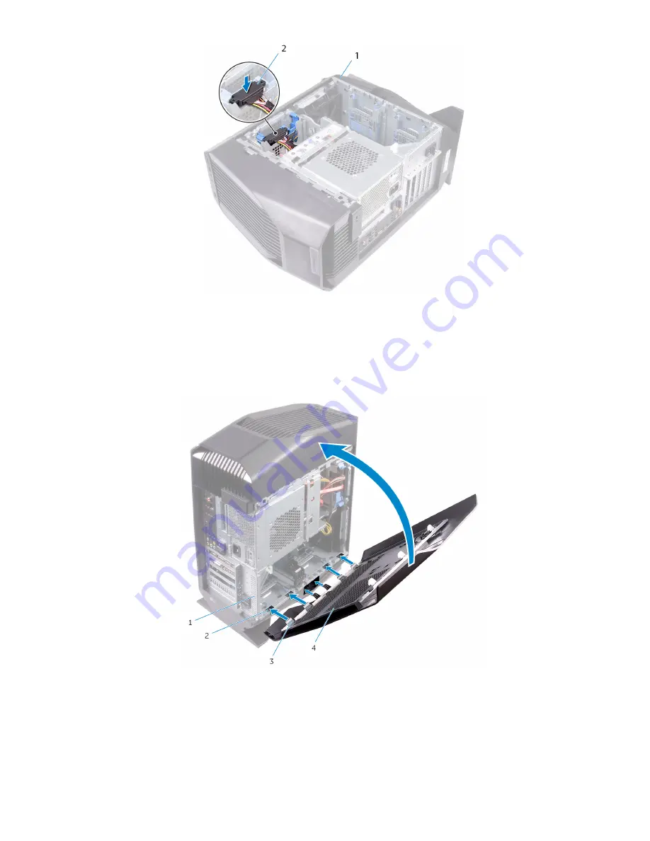
Figure 11. Connecting the power cable

1

chassis

2

power cable

26  Place the computer in an upright position.
27  Align the tabs on the left-side cover with the slots on the chassis.
28  Snap the left-side cover to lock it in place.

Figure 12. Replacing the left-side cover

1

chassis

2

slots

3

tabs

4

left-side cover

29  Replace the screw (#6-32 X 1/2") that secures the side-panel release latch to the chassis.

14

Installing the U.2 solid-state drive

Содержание Aurora R6

Страница 1: ...Aurora R6 R7 U 2 Solid State Drive Installation Guide Computer Model Alienware Aurora R7 Regulatory Model D23M Regulatory Type D23M001 ...

Страница 2: ...amage to hardware or loss of data and tells you how to avoid the problem WARNING A WARNING indicates a potential for property damage personal injury or death 2018 Dell Inc or its subsidiaries All rights reserved Dell EMC and other trademarks are trademarks of Dell Inc or its subsidiaries Other trademarks may be trademarks of their respective owners 2018 08 Rev A00 ...

Страница 3: ...r 4 Before you begin 4 Safety instructions 4 Recommended tools 5 2 Installing the U 2 solid state drive 6 3 After working inside your computer 15 4 Getting help and contacting Alienware 16 Self help resources 16 Contacting Alienware 16 Contents 3 ...

Страница 4: ...l com regulatory_compliance WARNING Disconnect all power sources before opening the computer cover or panels After you finish working inside the computer replace all covers panels and screws before connecting to the electrical outlet CAUTION To avoid damaging the computer ensure that the work surface is flat and clean CAUTION To avoid damaging the components and cards handle them by their edges an...

Страница 5: ... any installed card from the media card reader Recommended tools The procedures in this document may require the following tools Philips screwdriver 1 Flat head screwdriver Plastic scribe Before working inside your computer 5 ...

Страница 6: ...el release latch 3 Release the left side cover away from the chassis and then lift it from the computer Figure 1 Removing the left side cover 1 screw 2 side panel release latch 3 top cover 4 left side cover 4 Lay the computer on the right side 5 Disconnect the data and power cables from the hard drive 6 Press the release tabs on the hard drive carrier and slide the hard drive carrier out of the ha...

Страница 7: ...ase tabs 5 hard drive carrier 7 Place the U 2 solid state drive in the hard drive carrier and align the tabs on the carrier with the slots on the U 2 solid state drive Figure 3 Assembling the U 2 solid state drive 1 hard drive carrier 2 fan cable Installing the U 2 solid state drive 7 ...

Страница 8: ...te drive assembly 2 chassis 9 Slide the power supply unit cage release latches towards the unlock position Figure 5 Sliding the power supply unit cage release latches 1 power supply unit 2 chassis 3 power supply unit cage release cage latches 2 10 Lift the power supply unit cage while pressing and holding the graphics card bracket 8 Installing the U 2 solid state drive ...

Страница 9: ...Figure 6 Rotating the power supply unit 1 power supply unit cage 2 graphics card bracket 3 chassis 11 Rotate the power supply unit cage away from the chassis Installing the U 2 solid state drive 9 ...

Страница 10: ...Figure 7 Rotating the power supply unit 1 power supply unit 12 Lift to release the graphics card bracket from the chassis 10 Installing the U 2 solid state drive ...

Страница 11: ...Press the releasing clip on the power cable connectors and disconnect the power cables from the graphics card 14 Push the securing tab on the PCIe slot away from the graphics card grasp the card by its top corner and ease it out of the slot Installing the U 2 solid state drive 11 ...

Страница 12: ...y unit cage 16 Connect the fan cable to the system board 17 Connect the power cable to the power supply unit 18 Connect the data cable to the connector on the solid state drive adapter 19 Slide the solid state drive adapter to the solid state drive slot and replace the screw that secures the solid state drive adapter to the system board 12 Installing the U 2 solid state drive ...

Страница 13: ...s card into the slot and press down firmly until the graphics card snaps into place 22 Connect the power cables to the graphics card 23 Slide the tab on the graphics card bracket into the slot on the chassis and snap it into place 24 Rotate the power supply unit cage towards the chassis until the unit snaps into place 25 Connect the power cable to the U 2 solid state drive Installing the U 2 solid...

Страница 14: ...e tabs on the left side cover with the slots on the chassis 28 Snap the left side cover to lock it in place Figure 12 Replacing the left side cover 1 chassis 2 slots 3 tabs 4 left side cover 29 Replace the screw 6 32 X 1 2 that secures the side panel release latch to the chassis 14 Installing the U 2 solid state drive ...

Страница 15: ...y screws remain inside your computer 2 Connect any external devices peripherals or cables you removed before working on your computer 3 Replace any media cards discs or any other parts that you removed before working on your computer 4 Connect your computer and all attached devices to their electrical outlets 5 Turn on your computer 3 After working inside your computer 15 ...

Страница 16: ...tware updates and so on www alienware com gamingservices Videos providing step by step instructions to service your computer www youtube com alienwareservices Contacting Alienware To contact Alienware for sales technical support or customer service issues see www alienware com NOTE Availability varies by country and product and some services may not be available in your country NOTE If you do not ...

Отзывы: