background image

075

075

/

CHAPTER 17: DISPLAY 

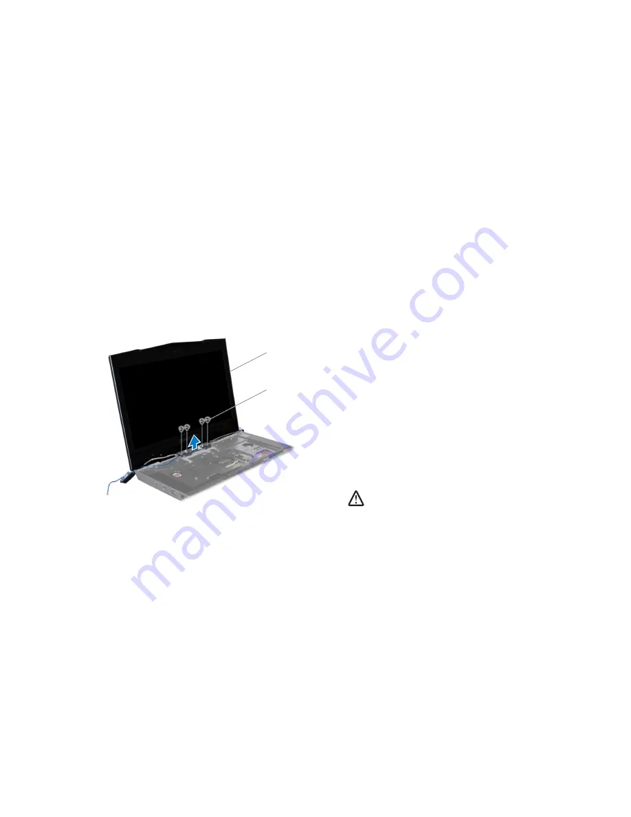
Replacing the Display Assembly

Follow the instructions in “Before You Begin” on page 

1. 

6

.

Align the screw holes on the display hinges with the screw holes on the 

2. 

computer base.

Replace the four screws (two on each hinge) that secure the display 

3. 

assembly to the computer base.

Route the Mini-Card antenna cables through the routing guides and 

4. 

connect them to the respective Mini-Cards.

Route the display and camera cables through the routing guides and 

5. 

connect them to the system board connectors.

Replace the two screws in the battery bay.

6. 

Replace the palm rest (see “Replacing the Palm Rest” on page 

7. 

3

9).

Replace the keyboard (see “Replacing the Keyboard” on page 

8. 

35

).

Replace the center control cover (see “Replacing the Center Control Cover” 

9. 

on page 

31

).

Replace the memory module(s) (see “Replacing the Memory Module(s)” on 

10. 

page 2

3

).

Replace the hard drive (see “Replacing the Hard Drive” on page 

11. 

18

).

Replace the compartment door (see “Replacing the Compartment Door” on 

12. 

page 

14

).

Replace the battery pack (see “Replacing the Battery Pack” on page 

13. 

8

). 

CAUTION: Before turning on the computer, replace all screws and 

ensure that no stray screws remain inside the computer. Failure to do 

so may result in damage to the computer.

Remove the four screws (two from each hinge) that secure the display 

13. 

assembly to the computer base.

Tilt the display assembly towards the computer base at a 45-degree angle 

14. 

and lift the display assembly off the computer.

1

2

1 display assembly

2 screws (4)

Содержание Alienware M15x

Страница 1: ...01 01 ALIENWARE M15x SERVICE MANUAL ...

Страница 2: ... United States and or other countries Bluetooth is a registered trademark owned by Bluetooth SIG Inc and is used by Dell under license Computrace and Absolute are registered trademarks of Absolute Software Corporation Other trademarks and trade names may be used in this manual to refer to either the entities claiming the marks and names or their products Dell Inc disclaims any proprietary interest...

Страница 3: ...rive 17 Replacing the Hard Drive 18 CHAPTER 5 MEMORY MODULE S 19 Removing the Memory Module s 21 Replacing the Memory Module s 23 CHAPTER 6 COIN CELL BATTERY 25 Removing the Coin Cell Battery 27 Replacing the Coin Cell Battery 27 CHAPTER 7 CENTER CONTROL COVER 28 Removing the Center Control Cover 30 Replacing the Center Control Cover 31 CHAPTER 8 KEYBOARD 32 Removing the Keyboard 34 Replacing the ...

Страница 4: ...T OUTPUT BOARD 86 Removing the Input Output Board 88 Replacing the Input Output Board 89 CHAPTER 11 WIRELESS MINI CARD S 44 Removing the Half Mini Card 46 Replacing the Half Mini Card 47 Removing the Full Mini Card 48 Replacing the Full Mini Card 49 CHAPTER 12 PROCESSOR FAN AND HEAT SINK ASSEMBLY 50 Removing the Processor Fan and Heat Sink Assembly 52 Replacing the Processor Fan and Heat Sink Asse...

Страница 5: ... 99 CHAPTER 22 SYSTEM BOARD 100 Removing the System Board 102 Replacing the System Board 104 CHAPTER 23 SPEAKERS 105 Removing the Speakers 107 Replacing the Speakers 107 CHAPTER 24 BATTERY LATCH ASSEMBLY 108 Removing the Battery Latch Assembly 110 Replacing the Battery Latch Assembly 110 CHAPTER 25 SYSTEM SETUP 111 Overview 112 Entering System Setup 112 System Setup Options 113 Flashing the BIOS 1...

Страница 6: ...ollowing conditions exist You have performed the steps in Turning Off Your Computer on page 7 and Before Working Inside Your Computer on page 8 You have read the safety information that shipped with your computer A component can be replaced or if purchased separately installed by performing the removal procedure in reverse order CHAPTER 1 BEFORE YOU BEGIN CHAPTER 1 BEFORE YOU BEGIN ...

Страница 7: ...lick Start click the arrow and then click Shut Down The computer turns off after the operating system shutdown process finishes Ensure that the computer is turned off If your computer did not 3 automatically turn off when you shut down the operating system press and hold the power button until the computer turns off Recommended Tools The procedures in this document may require the following tools ...

Страница 8: ...e following safety guidelines to help protect your computer from potential damage and to help to ensure your own personal safety WARNING Before you begin any of the procedures in this section follow the safety instructions that shipped with your computer For additional safety best practices information see the Regulatory Compliance Homepage at www dell com regulatory_compliance CAUTION Only a cert...

Страница 9: ...CHAPTER 2 BATTERY PACK 09 09 CHAPTER 2 BATTERY PACK CHAPTER 2 BATTERY PACK ...

Страница 10: ...uter disconnect the AC adapter from the electrical outlet and the computer disconnect the modem from the wall connector and the computer and remove any other external cables from the computer CAUTION To avoid electrostatic discharge ground yourself by using a wrist grounding strap or by periodically touching an unpainted metal surface such as a connector on the back of the computer CAUTION To help...

Страница 11: ... Turn the computer over 2 Slide the battery latch to the unlock position as shown 3 The battery pack will pop up 4 Remove the battery pack 5 Replacing the Battery Pack Follow the instructions in Before You Begin on page 1 6 Align the battery pack tabs with the slots in the battery bay 2 Push the battery pack into the battery bay until the battery pack clicks into 3 place ...

Страница 12: ...CHAPTER 3 COMPARTMENT DOOR 012 012 CHAPTER 3 COMPARTMENT DOOR CHAPTER 3 COMPARTMENT DOOR ...

Страница 13: ...nect the modem from the wall connector and the computer and remove any other external cables from the computer CAUTION Only a certified service technician should perform repairs on your computer Damage due to servicing that is not authorized by Dell is not covered by your warranty CAUTION To avoid electrostatic discharge ground yourself by using a wrist grounding strap or by periodically touching ...

Страница 14: ... that secure the compartment door to the computer 3 base Slide the compartment door towards the front of the computer and then lift 4 it up Replacing the Compartment Door Follow the instructions in Before You Begin on page 1 6 Place the compartment door on the computer base and slide it towards the 2 back of the computer Replace the two screws that secure the compartment door to the computer 3 bas...

Страница 15: ...CHAPTER 4 HARD DRIVE 015 015 CHAPTER 4 HARD DRIVE CHAPTER 4 HARD DRIVE ...

Страница 16: ...not authorized by Dell is not covered by your warranty CAUTION To prevent data loss turn off your computer see Turning Off Your Computer on page 7 before removing the hard drive Do not remove the hard drive while the computer is on or in Sleep state CAUTION Hard drives are extremely fragile Exercise care when handling the hard drive CAUTION To avoid electrostatic discharge ground yourself by using...

Страница 17: ... the Compartment Door on 3 page 14 Loosen the four captive screws that secure the hard drive assembly 4 Using the pull tab lift the hard drive assembly out of the hard drive bay 5 3 1 2 1 pull tab 3 captive screws 4 2 hard drive assembly Remove the four screws that secure the hard drive to the hard drive bracket 6 Lift the hard drive out of the hard drive bracket 7 3 1 2 1 hard drive 3 screws 4 2 ...

Страница 18: ...d drive bracket 4 Replace the four screws that secure the hard drive to the hard drive bracket 5 Place the hard drive assembly in the hard drive bay 6 Align and tighten the four captive screws that secure the hard drive 7 assembly to the hard drive bay Replace the compartment door see Replacing the Compartment Door on 8 page 14 Replace the battery pack see Replacing the Battery Pack on page 9 11 C...

Страница 19: ...ns at support dell com manuals for information on the memory supported by your computer Install only memory modules that are supported by your computer NOTE Memory modules purchased from Dell or Alienware are covered under your computer warranty Your computer has two user accessible SODIMM sockets that can be accessed from the bottom of the computer CHAPTER 5 MEMORY MODULE S CHAPTER 5 MEMORY MODUL...

Страница 20: ...ect the modem from the wall connector and the computer and remove any other external cables from the computer CAUTION Only a certified service technician should perform repairs on your computer Damage due to servicing that is not authorized by Dell is not covered by your warranty CAUTION To avoid electrostatic discharge ground yourself by using a wrist grounding strap or by periodically touching a...

Страница 21: ...oor on 3 page 14 Loosen the two captive screws that secure the memory module door to the 4 computer base Slide the memory module door to release the tabs and lift the 5 memory module door out of the computer base CAUTION If you need to remove memory modules from both connectors remove the memory module in the upper connector before you remove the module in the lower connector 4 3 2 1 1 slots 2 3 m...

Страница 22: ...ctor s do not use tools to spread the memory module spring locks Use your fingertips to carefully spread apart the spring locks on the 6 memory module connector until the memory module pops up Remove the memory module 7 1 2 4 5 3 1 memory module 3 memory module connector 2 spring locks 2 ...

Страница 23: ...not boot Replacing the Memory Module s CAUTION If you need to install memory modules in two connectors install a memory module in the lower connector before you install a module in the upper connector Follow the instructions in Before You Begin on page 1 6 Align the notch on the memory module with the tab on the memory module 2 connector Insert the module into the memory module connector at a 45 d...

Страница 24: ...cing the Battery Pack on page 7 11 CAUTION Before turning on the computer replace all screws and ensure that no stray screws remain inside the computer Failure to do so may result in damage to the computer Turn on the computer 8 As the computer boots it detects the additional memory and automatically updates the system configuration information To confirm the amount of memory installed in the comp...

Страница 25: ...CHAPTER 6 COIN CELL BATTERY 025 025 CHAPTER 6 COIN CELL BATTERY CHAPTER 6 COIN CELL BATTERY ...

Страница 26: ...nnect the modem from the wall connector and the computer and remove any other external cables from the computer CAUTION Only a certified service technician should perform repairs on your computer Damage due to servicing that is not authorized by Dell is not covered by your warranty CAUTION To avoid electrostatic discharge ground yourself by using a wrist grounding strap or by periodically touching...

Страница 27: ...base Disconnect the coin cell battery cable from the system board connector 5 Replacing the Coin Cell Battery Follow the instructions in Before You Begin on page 1 6 Connect the coin cell battery cable to the system board connector 2 Use the adhesive on the coin cell battery and adhere it to the computer 3 base Replace the compartment door see Replacing the Compartment Door on 4 page 14 Replace th...

Страница 28: ...CHAPTER 7 CENTER CONTROL COVER 028 028 CHAPTER 7 CENTER CONTROL COVER CHAPTER 7 CENTER CONTROL COVER ...

Страница 29: ...sconnect the modem from the wall connector and the computer and remove any other external cables from the computer CAUTION Only a certified service technician should perform repairs on your computer Damage due to servicing that is not authorized by Dell is not covered by your warranty CAUTION To avoid electrostatic discharge ground yourself by using a wrist grounding strap or by periodically touch...

Страница 30: ...odule s on 5 page 21 Remove the two screws that secure the center control cover to the 6 computer base Turn the computer top side up and open the display as far as possible 7 CAUTION Be extremely careful when removing the center control cover The center control cover along with the cable that attaches it to the system board connector are very fragile Pry the center control cover up with a plastic ...

Страница 31: ...er base Replace the memory module s see Replacing the Memory Module s on 5 page 23 Replace the hard drive see Replacing the Hard Drive on page 6 18 Replace the compartment door see Replacing the Compartment Door on 7 page 14 Replace the battery pack see Replacing the Battery Pack on page 8 11 CAUTION Before turning on the computer replace all screws and ensure that no stray screws remain inside th...

Страница 32: ...CHAPTER 8 KEYBOARD 032 032 CHAPTER 8 KEYBOARD CHAPTER 8 KEYBOARD ...

Страница 33: ... modem from the wall connector and the computer and remove any other external cables from the computer CAUTION Only a certified service technician should perform repairs on your computer Damage due to servicing that is not authorized by Dell is not covered by your warranty CAUTION To avoid electrostatic discharge ground yourself by using a wrist grounding strap or by periodically touching an unpai...

Страница 34: ...ge 4 17 Remove the memory module s see Removing the Memory Module s on 5 page 21 Remove the center control cover see Removing the Center Control Cover 6 on page 30 Remove the three screws that secure the keyboard to the computer 7 CAUTION Be extremely careful when removing and handling the keyboard Failure to do so could result in scratching the display panel The keyboard along with the cables tha...

Страница 35: ... memory module s see Replacing the Memory Module s on 6 page 23 Replace the hard drive see Replacing the Hard Drive on page 7 18 Replace the compartment door see Replacing the Compartment Door on 8 page 14 Replace the battery pack see Replacing the Battery Pack on page 9 11 CAUTION Before turning on the computer replace all screws and ensure that no stray screws remain inside the computer Failure ...

Страница 36: ...CHAPTER 9 PALM REST 036 036 CHAPTER 9 PALM REST CHAPTER 9 PALM REST ...

Страница 37: ...e modem from the wall connector and the computer and remove any other external cables from the computer CAUTION Only a certified service technician should perform repairs on your computer Damage due to servicing that is not authorized by Dell is not covered by your warranty CAUTION To avoid electrostatic discharge ground yourself by using a wrist grounding strap or by periodically touching an unpa...

Страница 38: ... see Removing the Memory Module s on 5 page 21 Remove the two screws that secure the palm rest to the computer base 6 Turn the computer top side up and open the display as far as possible 7 CAUTION Be extremely careful when removing the palm rest The palm rest along with the cable that connects the touch pad to the system board connector are very fragile Slide and lift the palm rest out as shown i...

Страница 39: ... connector latch to secure the cable to the connector Press and slide the palm rest into position 3 Turn the computer over and replace the two screws that secure the palm 4 rest to the computer base Replace the memory module s see Replacing the Memory Module s on 5 page 23 Replace the hard drive see Replacing the Hard Drive on page 6 18 Replace the compartment door see Replacing the Compartment Do...

Страница 40: ...CHAPTER 10 AIR VENTS 040 040 CHAPTER 10 AIR VENTS CHAPTER 10 AIR VENTS ...

Страница 41: ...e modem from the wall connector and the computer and remove any other external cables from the computer CAUTION Only a certified service technician should perform repairs on your computer Damage due to servicing that is not authorized by Dell is not covered by your warranty CAUTION To avoid electrostatic discharge ground yourself by using a wrist grounding strap or by periodically touching an unpa...

Страница 42: ...emove the compartment door see Removing the Compartment Door on 3 page 14 Remove the hard drive see Removing the Hard Drive on page 4 17 Remove the memory module s see Removing the Memory Module s on 5 page 21 Remove the center control cover see Removing the Center Control Cover 6 on page 30 Remove the four screws that secure the air vents to the computer base 7 1 1 screws 4 ...

Страница 43: ...ge 31 Replace the memory module s see Replacing the Memory Module s on 6 page 23 Replace the hard drive see Replacing the Hard Drive on page 7 18 Replace the compartment door see Replacing the Compartment Door on 8 page 14 Replace the battery pack see Replacing the Battery Pack on page 9 11 CAUTION Before turning on the computer replace all screws and ensure that no stray screws remain inside the ...

Страница 44: ...l Area Network WLAN Half Mini Card Wireless Personal Area Network WPAN or Internal Card with Bluetooth Wireless Technology Full Mini Card NOTE The WLAN slot supports a half Mini Card NOTE Depending on the configuration of the computer when it was sold one or more of the Mini Card slots may not have Mini Cards installed in them CHAPTER 11 WIRELESS MINI CARD S CHAPTER 11 WIRELESS MINI CARD S ...

Страница 45: ...sconnect the modem from the wall connector and the computer and remove any other external cables from the computer CAUTION Only a certified service technician should perform repairs on your computer Damage due to servicing that is not authorized by Dell is not covered by your warranty CAUTION To avoid electrostatic discharge ground yourself by using a wrist grounding strap or by periodically touch...

Страница 46: ...Removing the Half Mini Card Follow the instructions in Before You Begin on page 1 6 Remove the battery pack see Removing the Battery Pack on page 2 8 Remove the compartment door see Removing the Compartment Door on 3 page 14 Remove the hard drive see Removing the Hard Drive on page 4 17 Remove the memory module s see Removing the Memory Module s on 5 page 21 Remove the center control cover see Rem...

Страница 47: ...firm and even pressure to slide the card into place If you use excessive force you may damage the connector Align the notch on the card with the tab on the system board connector 3 Insert the half Mini Card at a 45 degree angle into the appropriate system 4 board connector For example the WLAN card connector is labeled WLAN and so on Press the other end of the half Mini Card down into the slot on ...

Страница 48: ... that shipped with your computer Removing the Full Mini Card Follow the instructions in Before You Begin on page 1 6 Remove the battery pack see Removing the Battery Pack on page 2 11 Remove the compartment door see Removing the Compartment Door on 3 page 14 Remove the hard drive see Removing the Hard Drive on page 4 17 Remove the memory module s see Removing the Memory Module s on 5 page 21 Remov...

Страница 49: ...from a source other than Dell or Alienware you must install the appropriate drivers and utilities Replacing the Full Mini Card Follow the instructions in Before You Begin on page 1 6 Remove the new full Mini Card from its packaging 2 CAUTION Use firm and even pressure to slide the card into place If you use excessive force you may damage the connector Align the notch on the card with the tab on th...

Страница 50: ...CHAPTER 12 PROCESSOR FAN AND HEAT SINK ASSEMBLY 050 050 CHAPTER 12 PROCESSOR FAN AND HEAT SINK ASSEMBLY CHAPTER 12 PROCESSOR FAN AND HEAT SINK ASSEMBLY ...

Страница 51: ... the computer disconnect the modem from the wall connector and the computer and remove any other external cables from the computer CAUTION Only a certified service technician should perform repairs on your computer Damage due to servicing that is not authorized by Dell is not covered by your warranty CAUTION To avoid electrostatic discharge ground yourself by using a wrist grounding strap or by pe...

Страница 52: ...artment door see Removing the Compartment Door on 3 page 14 Remove the hard drive see Removing the Hard Drive on page 4 17 Remove the memory module s see Removing the Memory Module s on 5 page 21 Remove the center control cover see Removing the Center Control Cover 6 on page 30 Remove the right air vent see Removing the Air Vents on page 7 42 Loosen the captive screw that secures the processor fan...

Страница 53: ...captive screws 4 Disconnect the processor fan and heat sink assembly cable from the system 9 board connector In sequential order indicated on the processor fan and heat sink assembly 10 loosen the four captive screws that secure the processor fan and heat sink assembly to the system board Lift the processor fan and heat sink assembly off the system board 11 ...

Страница 54: ...computer Replacing the Processor Fan and Heat Sink Assembly Follow the instructions in Before You Begin on page 1 6 Peel the backing off the thermal cooling pads attached to the new processor 2 fan and heat sink assembly NOTE If the processor fan and heat sink assembly is replaced the thermal cooling pads will be attached to the new processor fan and heat sink assembly Do not reuse the old thermal...

Страница 55: ...CHAPTER 13 PROCESSOR 055 055 CHAPTER 13 PROCESSOR CHAPTER 13 PROCESSOR ...

Страница 56: ...revent damage to the system board remove the main battery see Removing the Battery Pack on page 11 before working inside the computer Processor WARNING Before working inside your computer read the safety information that shipped with your computer For additional safety best practices information see the Regulatory Compliance Homepage at www dell com regulatory_compliance WARNING Before performing ...

Страница 57: ...emove the center control cover see Removing the Center Control Cover 6 on page 30 Remove the right air vent see Removing the Air Vents on page 7 42 Remove the processor fan and heat sink assembly see Removing the 8 Processor Fan and Heat Sink Assembly on page 52 CAUTION When removing the processor pull it straight up Be careful not to bend the pins on the processor To loosen the ZIF socket use a s...

Страница 58: ... 6 CAUTION Ensure that the cam lock is in the fully open position before seating the processor Seating the processor properly in the ZIF socket does not require force CAUTION A processor that is not properly seated can result in an intermittent connection or permanent damage to the processor and ZIF socket Align the pin 1 corner of the processor so that it points to the triangle on the 2 ZIF socke...

Страница 59: ...CHAPTER 14 GRAPHICS CARD FAN 059 059 CHAPTER 14 GRAPHICS CARD FAN CHAPTER 14 GRAPHICS CARD FAN ...

Страница 60: ...nnect the modem from the wall connector and the computer and remove any other external cables from the computer CAUTION Only a certified service technician should perform repairs on your computer Damage due to servicing that is not authorized by Dell is not covered by your warranty CAUTION To avoid electrostatic discharge ground yourself by using a wrist grounding strap or by periodically touching...

Страница 61: ...pack see Removing the Battery Pack on page 2 11 Remove the compartment door see Removing the Compartment Door on 3 page 14 Remove the hard drive see Removing the Hard Drive on page 4 17 Remove the memory module s see Removing the Memory Module s on 5 page 21 Loosen the two captive screws that secure the graphics card fan to the 6 computer base ...

Страница 62: ...mory Module s on 5 page 23 Replace the hard drive see Replacing the Hard Drive on page 6 18 Replace the compartment door see Replacing the Compartment Door on 7 page 14 Replace the battery pack see Replacing the Battery Pack on page 8 11 CAUTION Before turning on the computer replace all screws and ensure that no stray screws remain inside the computer Failure to do so may result in damage to the ...

Страница 63: ...CHAPTER 15 GRAPHICS CARD HEAT SINK 063 063 CHAPTER 15 GRAPHICS CARD HEAT SINK CHAPTER 15 GRAPHICS CARD HEAT SINK ...

Страница 64: ... disconnect the modem from the wall connector and the computer and remove any other external cables from the computer CAUTION Only a certified service technician should perform repairs on your computer Damage due to servicing that is not authorized by Dell is not covered by your warranty CAUTION To avoid electrostatic discharge ground yourself by using a wrist grounding strap or by periodically to...

Страница 65: ...emoving the Hard Drive on page 4 17 Remove the memory module s see Removing the Memory Module s on 5 page 21 Remove the center control cover see Removing the Center Control Cover 6 on page 30 Remove the left air vent see Removing the Air Vents on page 7 42 Remove the graphics card fan see Removing the Graphics Card Fan on 8 page 61 In sequential order indicated on the graphics card heat sink loose...

Страница 66: ...hics Card Fan on 4 page 62 Replace the left air vent see Replacing the Air Vents on page 5 43 Replace the center control cover see Replacing the Center Control Cover 6 on page 31 Replace the memory module s see Replacing the Memory Module s on 7 page 23 Replace the hard drive see Replacing the Hard Drive on page 8 18 Replace the compartment door see Replacing the Compartment Door on 9 page 14 Repl...

Страница 67: ...CHAPTER 16 GRAPHICS CARD 067 067 CHAPTER 16 GRAPHICS CARD CHAPTER 16 GRAPHICS CARD ...

Страница 68: ...t the modem from the wall connector and the computer and remove any other external cables from the computer CAUTION Only a certified service technician should perform repairs on your computer Damage due to servicing that is not authorized by Dell is not covered by your warranty CAUTION To avoid electrostatic discharge ground yourself by using a wrist grounding strap or by periodically touching an ...

Страница 69: ...ve on page 4 17 Remove the memory module s see Removing the Memory Module s on 5 page 21 Remove the center control cover see Removing the Center Control Cover 6 on page 30 Remove the left air vent see Removing the Air Vents on page 7 42 Remove the graphics card fan see Removing the Graphics Card Fan on 8 page 61 Remove the graphics card heat sink see Removing the Graphics Card Heat 9 Sink on page ...

Страница 70: ...Fan on 5 page 62 Replace the left air vent see Replacing the Air Vents on page 6 43 Replace the center control cover see Replacing the Center Control Cover 7 on page 31 Replace the memory module s see Replacing the Memory Module s on 8 page 23 Replace the hard drive see Replacing the Hard Drive on page 9 18 Replace the compartment door see Replacing the Compartment Door on 10 page 14 Replace the b...

Страница 71: ...CHAPTER 17 DISPLAY 071 071 CHAPTER 17 DISPLAY CHAPTER 17 DISPLAY ...

Страница 72: ...e any other external cables from the computer CAUTION Only a certified service technician should perform repairs on your computer Damage due to servicing that is not authorized by Dell is not covered by your warranty CAUTION To avoid electrostatic discharge ground yourself by using a wrist grounding strap or by periodically touching an unpainted metal surface such as a connector on the back of the...

Страница 73: ... page 14 Remove the hard drive see Removing the Hard Drive on page 4 17 Remove the memory module s see Removing the Memory Module s on 5 page 21 Remove the center control cover see Removing the Center Control Cover 6 on page 30 Remove the keyboard see Removing the Keyboard on page 7 34 Remove the palm rest see Removing the Palm Rest on page 8 38 Remove the two screws from the battery bay 9 Turn th...

Страница 74: ... 2 camera cable connector Disconnect the antenna cables from the respective Mini Cards and remove 11 these cables from their routing guides Disconnect the display cable and the camera cable from the respective 12 system board connectors and remove these cables from their routing guides ...

Страница 75: ...board see Replacing the Keyboard on page 8 35 Replace the center control cover see Replacing the Center Control Cover 9 on page 31 Replace the memory module s see Replacing the Memory Module s on 10 page 23 Replace the hard drive see Replacing the Hard Drive on page 11 18 Replace the compartment door see Replacing the Compartment Door on 12 page 14 Replace the battery pack see Replacing the Batter...

Страница 76: ...eplacing the Display Assembly on 5 page 75 CAUTION Before turning on the computer replace all screws and ensure that no stray screws remain inside the computer Failure to do so may result in damage to the computer Display Hinge Cover Removing the Display Hinge Cover Follow the instructions in Before You Begin on page 1 6 Remove the display assembly see Removing the Display Assembly on 2 page 73 Re...

Страница 77: ...r on 3 page 76 Remove the seven screws that secure the display panel to the display back 4 cover NOTE Use a dry lint free soft cloth while removing or replacing the display panel to avoid smudging the display panel Slide the display panel towards the display hinges to release it from the 5 display back cover Lift the display panel up and move it towards the top of the display back 6 cover 2 3 4 1 ...

Страница 78: ...ace the display panel and slide the display panel towards the top of the 3 display back cover Replace the seven screws that secure the display panel to the display back 4 cover Replace the display hinge cover see Replacing the Display Hinge Cover on 5 page 76 Replace the display assembly see Replacing the Display Assembly on 6 page 75 Disconnect the AlienHead cable connector and lift the display p...

Страница 79: ...ee Removing the Display Assembly on 2 page 73 Remove the display hinge cover see Removing the Display Hinge Cover on 3 page 76 Remove the display panel see Removing the Display Panel on page 4 77 Remove the two screws that secure the AlienHead board to the display back 5 cover Lift the top of the AlienHead board to release it from the tabs that hold it in 6 place Slide the AlienHead board down and...

Страница 80: ...hat secure the AlienHead board to the display back 3 cover Replace the display panel see Replacing the Display Panel on page 4 78 Replace the display hinge cover see Replacing the Display Hinge Cover on 5 page 76 Replace the display assembly see Replacing the Display Assembly on 6 page 75 CAUTION Before turning on the computer replace all screws and ensure that no stray screws remain inside the co...

Страница 81: ...CHAPTER 18 MAGNESIUM COVER 081 081 CHAPTER 18 MAGNESIUM COVER CHAPTER 18 MAGNESIUM COVER ...

Страница 82: ...ect the modem from the wall connector and the computer and remove any other external cables from the computer CAUTION Only a certified service technician should perform repairs on your computer Damage due to servicing that is not authorized by Dell is not covered by your warranty CAUTION To avoid electrostatic discharge ground yourself by using a wrist grounding strap or by periodically touching a...

Страница 83: ...n page 2 11 Remove the compartment door see Removing the Compartment Door on 3 page 14 Remove the hard drive see Removing the Hard Drive on page 4 17 Remove the memory module s see Removing the Memory Module s on 5 page 21 Remove the graphics card fan see Removing the Graphics Card Fan on 6 page 61 Remove the four screws that secure the magnesium cover to the computer 7 base ...

Страница 84: ...see Removing the Palm Rest on page 10 38 Remove the display assembly see Removing the Display Assembly on 11 page 73 Release the ExpressCard connector latch and disconnect the ExpressCard 12 cable from the system board connector Press and eject any installed cards from the ExpressCard slot and the 8 in 1 13 Media Card Reader before removing the magnesium cover Remove the twelve screws that secure ...

Страница 85: ...uter Failure to do so may result in damage to the computer Replacing the Magnesium Cover Follow the instructions in Before You Begin on page 1 6 Replace the magnesium cover on the computer base 2 Replace the twelve screws that secure the magnesium cover to the 3 computer base Replace any cards that were ejected from the ExpressCard slot and the 4 8 in 1 Media Card Reader Connect the ExpressCard ca...

Страница 86: ...CHAPTER 19 INPUT OUTPUT BOARD 086 086 CHAPTER 19 INPUT OUTPUT BOARD CHAPTER 19 INPUT OUTPUT BOARD ...

Страница 87: ...onnect the modem from the wall connector and the computer and remove any other external cables from the computer CAUTION Only a certified service technician should perform repairs on your computer Damage due to servicing that is not authorized by Dell is not covered by your warranty CAUTION To avoid electrostatic discharge ground yourself by using a wrist grounding strap or by periodically touchin...

Страница 88: ...ng the Memory Module s on 5 page 21 Remove the center control cover see Removing the Center Control Cover 6 on page 30 Remove the keyboard see Removing the Keyboard on page 7 34 Remove the palm rest see Removing the Palm Rest on page 8 38 Remove the display assembly see Removing the Display Assembly on 9 page 73 Remove the magnesium cover see Removing the Magnesium Cover on 10 page 83 Release the ...

Страница 89: ...he computer Failure to do so may result in damage to the computer Replacing the Input Output Board Follow the instructions in Before You Begin on page 1 6 Align the connectors on the input output board with the slots on the 2 computer Replace the two screws that secure the input output board to the computer 3 base Connect the audio cable to the system board connector and push down the 4 audio cabl...

Страница 90: ...CHAPTER 20 CONSUMER IR BOARD 090 090 CHAPTER 20 CONSUMER IR BOARD CHAPTER 20 CONSUMER IR BOARD ...

Страница 91: ...nnect the modem from the wall connector and the computer and remove any other external cables from the computer CAUTION Only a certified service technician should perform repairs on your computer Damage due to servicing that is not authorized by Dell is not covered by your warranty CAUTION To avoid electrostatic discharge ground yourself by using a wrist grounding strap or by periodically touching...

Страница 92: ...y module s see Removing the Memory Module s on 5 page 21 Remove the center control cover see Removing the Center Control Cover 6 on page 30 Remove the keyboard see Removing the Keyboard on page 7 34 Remove the palm rest see Removing the Palm Rest on page 8 38 Remove the display assembly see Removing the Display Assembly on 9 page 73 Remove the magnesium cover see Removing the Magnesium Cover on 10...

Страница 93: ...hat no stray screws remain inside the computer Failure to do so may result in damage to the computer Replacing the Consumer IR Board Follow the instructions in Before You Begin on page 1 6 Align the consumer IR board with the guide posts on the computer base 2 Replace the two screws that secure the consumer IR board to the computer 3 base Connect the consumer IR board cable to the system board con...

Страница 94: ...CHAPTER 21 OPTICAL DRIVE 094 094 CHAPTER 21 OPTICAL DRIVE CHAPTER 21 OPTICAL DRIVE ...

Страница 95: ...t the modem from the wall connector and the computer and remove any other external cables from the computer CAUTION Only a certified service technician should perform repairs on your computer Damage due to servicing that is not authorized by Dell is not covered by your warranty CAUTION To avoid electrostatic discharge ground yourself by using a wrist grounding strap or by periodically touching an ...

Страница 96: ...ing the Magnesium Cover on 11 page 83 Remove the input output board see Removing the Input Output Board on 12 page 88 Removing the Optical Drive Follow the instructions in Before You Begin on page 1 6 Remove the battery pack see Removing the Battery Pack on page 2 11 Remove the compartment door see Removing the Compartment Door on 3 page 14 Remove the hard drive see Removing the Hard Drive on page...

Страница 97: ... 2 3 1 1 optical drive 3 screws 5 2 optical drive bracket Remove the three screws that secure the optical drive to the computer base 13 Release the connector latch and disconnect the optical drive cable from the 14 system board connector Lift the optical drive out of the computer 15 1 2 3 4 1 screws 3 3 optical drive cable 2 optical drive 4 connector latch ...

Страница 98: ...098 098 CHAPTER 21 OPTICAL DRIVE Disconnect the optical drive cable from the optical drive 17 1 2 1 optical drive 2 optical drive cable ...

Страница 99: ...replace all screws and ensure that no stray screws remain inside the computer Failure to do so may result in damage to the computer Replacing the Optical Drive Follow the instructions in Before You Begin on page 1 6 Connect the optical drive cable to the optical drive 2 Replace the five screws that secure the optical drive to the optical drive 3 bracket Place the optical drive in the computer base...

Страница 100: ... chip contains the Service Tag which is also visible on a barcode label on the bottom of the computer The Service Tag has to be entered in the replacement system board s BIOS chip using the System Setup utility CHAPTER 22 SYSTEM BOARD CHAPTER 22 SYSTEM BOARD ...

Страница 101: ...computer and remove any other external cables from the computer CAUTION Only a certified service technician should perform repairs on your computer Damage due to servicing that is not authorized by Dell is not covered by your warranty CAUTION To avoid electrostatic discharge ground yourself by using a wrist grounding strap or by periodically touching an unpainted metal surface such as a connector ...

Страница 102: ...ure the system board to the computer base 21 Lift the system board at an angle and remove it from the computer base 22 Removing the System Board Follow the instructions in Before You Begin on page 1 6 Remove the battery pack see Removing the Battery Pack on page 2 11 Remove the compartment door see Removing the Compartment Door on 3 page 14 Remove the hard drive see Removing the Hard Drive on page...

Страница 103: ...STEM BOARD 1 audio cable 5 consumer IR board cable connector 2 optical drive cable 6 left speaker light cable connector 3 right speaker light cable connector 7 system board 4 speaker cable connector 8 screws 5 1 2 3 4 5 6 7 8 ...

Страница 104: ...ervice Tag in the 24 Set Service Tag field of the System Setup For more information see System Setup Options on page 113 Replacing the System Board Follow the instructions in Before You Begin on page 1 6 Align the connectors on the system board with the slots on the computer 2 Replace the five screws that secure the system board to the computer base 3 Connect the following cables to their respecti...

Страница 105: ...CHAPTER 23 SPEAKERS 0105 0105 CHAPTER 23 SPEAKERS CHAPTER 23 SPEAKERS ...

Страница 106: ...e modem from the wall connector and the computer and remove any other external cables from the computer CAUTION Only a certified service technician should perform repairs on your computer Damage due to servicing that is not authorized by Dell is not covered by your warranty CAUTION To avoid electrostatic discharge ground yourself by using a wrist grounding strap or by periodically touching an unpa...

Страница 107: ...es 3 Lift the speakers off the computer base 4 Replacing the Speakers Follow the instructions in Before You Begin on page 1 6 Place the speakers on the computer base 2 Route the speaker cables into the routing guides 3 Replace the system board see Replacing the System Board on page 4 104 CAUTION Before turning on the computer replace all screws and ensure that no stray screws remain inside the com...

Страница 108: ...CHAPTER 24 BATTERY LATCH ASSEMBLY 0108 0108 CHAPTER 24 BATTERY LATCH ASSEMBLY CHAPTER 24 BATTERY LATCH ASSEMBLY ...

Страница 109: ... disconnect the modem from the wall connector and the computer and remove any other external cables from the computer CAUTION Only a certified service technician should perform repairs on your computer Damage due to servicing that is not authorized by Dell is not covered by your warranty CAUTION To avoid electrostatic discharge ground yourself by using a wrist grounding strap or by periodically to...

Страница 110: ...mputer base 5 Replacing the Battery Latch Assembly Follow the instructions in Before You Begin on page 1 6 Place the battery latch assembly in the channel in the computer base 2 Replace the screw that secures the battery latch to the battery latch 3 assembly Using a screwdriver place the spring over the hook on the computer base 4 Ensure that the newly installed battery latch assembly moves smooth...

Страница 111: ...CHAPTER 25 SYSTEM SETUP 0111 0111 CHAPTER 25 SYSTEM SETUP CHAPTER 25 SYSTEM SETUP ...

Страница 112: ...em Setup screen appears System Setup Screens The System Setup window displays current or changeable configuration information for your laptop Information is divided into five menus Main Advanced Security Boot and Exit Key functions appear at the bottom of the System Setup window and lists keys and their functions within the active field Overview The System Setup options allow you to Change the sys...

Страница 113: ...e but will greatly reduce battery life Wired Network Allows you to enable or disable the on board LAN controller Disabled Internal LAN is off and is not visible to the operating system Enabled Internal LAN is enabled System Setup Options NOTE Depending on your computer and installed devices the items listed in this section may not appear or may not appear exactly as listed Main Menu System Time Di...

Страница 114: ...d is not visible to the operating system Enabled The internal wireless device is enabled Bluetooth Receiver Allows you to enable or disable the internal Bluetooth device Disabled The internal Bluetooth device is off and is not visible to the operating system Enabled The internal Bluetooth device is enabled High Definition Sound Allows you to enable or disable the internal high definition audio dev...

Страница 115: ...e or disable password entry on boot Asset Tag Displays the asset tag Performance Options Sub Menu CPU Speed Displays the speed of the processor Memory Frequency Displays the frequency of the memory Memory Channel Mode Displays the memory channel modes Single Dual CPU Performance Mode Indicates if the processor is in turbo mode or not Turbo Mode Allows you to enable or disable the turbo mode Select...

Страница 116: ... Security Menu Computrace Allows you to activate or disable the BIOS module interface of the optional Computrace Service from Absolute Software The Computrace agent from Absolute Software is a service solution designed to help track assets and provide recovery services in the event the computer is lost or stolen The Computrace agent communicates with the Absolute software Monitoring Server at prog...

Страница 117: ...ur changes to CMOS Exit Discarding Changes Allows you to exit utility without saving Setup data to CMOS Load Setup Defaults Allows you to load default values for all Setup items Discard Changes Allows you to load previous values from CMOS for all Setup items Save Changes Allows you to save Setup data to CMOS ...

Страница 118: ... desktop Click 10 Close if the Download Complete window appears The file icon appears on your desktop and is titled the same as the downloaded BIOS update file Double click the file icon on the desktop and follow the instructions on the 11 screen Flashing the BIOS The BIOS may require flashing when an update is available or when replacing the system board To flash the BIOS Ensure that the AC adapt...

Отзывы: