background image

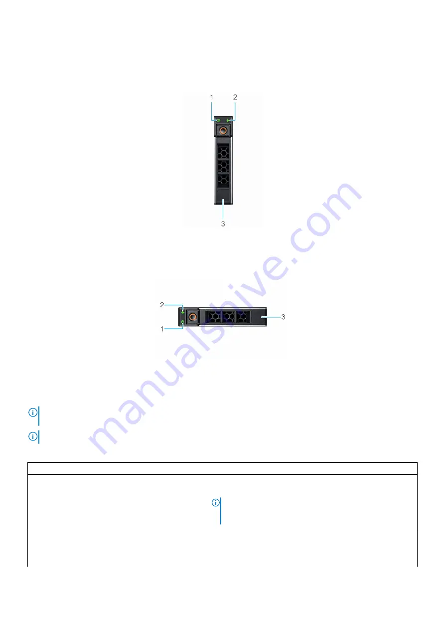
Drive indicator codes

The LEDs on the drive carrier indicates the state of each drive. Each drive carrier has two LEDs: an activity LED (green) and a status LED
(bicolor, green/amber). The activity LED blinks whenever the drive is accessed.

Figure 111. Drive indicators on the drive and the mid drive tray backplane

1. Drive activity LED indicator
2. Drive status LED indicator
3. Drive capacity label

Figure 112. Drive indicators

1. Drive activity LED indicator
2. Drive status LED indicator
3. Drive capacity label

NOTE:

 If the drive is in the Advanced Host Controller Interface (AHCI) mode, the status LED indicator does not power

on.

NOTE:

 Drive status indicator behavior is managed by Storage Spaces Direct. Not all drive status indicators may be used.

Table 95. Drive indicator codes 

Drive status indicator code

Condition

Blinks green twice per second

Indicates that the drive is being identified or preparing for removal.

Off

Indicates that the drive is ready for removal.

NOTE:

 The drive status indicator remains off until all drives

are initialized after the system is powered on. Drives are not
ready for removal during this time.

Blinks green, amber, and then powers off

Indicates that there is an expected drive failure.

Blinks amber four times per second

Indicates that the drive has failed.

Blinks green slowly

Indicates that the drive is rebuilding.

150

System diagnostics and indicator codes

Содержание XC Core XC6515

Страница 1: ...Dell EMC XC Core XC6515 Installation and Service Manual July 2020 Rev 1 0 ...

Страница 2: ...ential damage to hardware or loss of data and tells you how to avoid the problem WARNING A WARNING indicates a potential for property damage personal injury or death 2020 Dell Inc or its subsidiaries All rights reserved Dell EMC and other trademarks are trademarks of Dell Inc or its subsidiaries Other trademarks may be trademarks of their respective owners ...

Страница 3: ...ns to set up the iDRAC IP address 29 Options to log in to the iDRAC 30 Resources to install the operating system 30 Options to download firmware 31 Options to download and install operating system drivers 31 Downloading drivers and firmware 32 Chapter 5 Pre operating system management applications 33 System setup 33 System BIOS 34 iDRAC settings utility 50 Device settings 50 Lifecycle controller 5...

Страница 4: ...rive backplane 68 Remove the drive backplane 69 Install the drive backplane 70 Cable routing 72 System memory 72 System memory guidelines 72 General memory module installation guidelines 73 Remove a memory module 77 Install a memory module 78 Processor and heat sink 79 Remove the heat sink 79 Remove the AMD processor 80 Install the AMD processor 82 Install the heat sink 84 Expansion cards and expa...

Страница 5: ...power interposer board 114 Install the power interposer board 114 System board 115 Remove the system board 115 Install the system board 116 Restore the service tag 118 Trusted platform module 119 Upgrade the trusted platform module 119 Initialize the trusted platform module for users 119 Initialize the trusted platform module for 1 2 TXT users 119 Initialize the trusted platform module for 2 0 TXT...

Страница 6: ...specifications 140 Thermal restriction matrix 141 Chapter 9 System diagnostics and indicator codes 143 System diagnostics and indicator codes 143 Status LED indicators 143 System health and system ID indicator codes 144 iDRAC Direct LED indicator codes 145 LCD panel 145 Viewing Home screen 146 Setup menu 146 View menu 146 NIC indicator codes 147 Power supply unit indicator codes 148 Drive indicato...

Страница 7: ...he system cover 56 19 Installing the system cover 57 20 Removing the drive backplane cover 58 21 Installing the drive backplane cover 59 22 Removing the air shroud 60 23 Installing the air shroud 60 24 Removing a cooling fan 61 25 Installing a cooling fan 62 26 Removing the intrusion switch 63 27 Installing the intrusion switch 64 28 Removing a drive blank 64 29 Installing a drive blank 65 30 Remo...

Страница 8: ...from a low profile left riser 92 60 Removing a filler bracket from a low profile right riser 92 61 Installing an expansion card into a low profile left riser 93 62 Installing an expansion card into a low profile right riser 93 63 Removing the MicroSD card 94 64 Installing the MicroSD card 95 65 Removing the M 2 SSD module 96 66 Installing the M 2 SSD module 97 67 Removing the IDSDM module 98 68 In...

Страница 9: ...e cable cover 122 96 Removing the right control panel 122 97 Installing the cable cover 123 98 Installing the right control panel 124 99 System board connectors 125 100 System board connectors 127 101 System board jumpers and connectors 128 102 System board jumpers and connectors 129 103 Chassis dimensions 133 104 Status LED indicators 143 105 System health and system ID indicator 144 106 LCD pane...

Страница 10: ...ils 35 17 Processor Settings details 36 18 Processor n details 37 19 SATA Settings details 37 20 Port n 37 21 Boot Settings details 38 22 UEFI Boot Settings 38 23 Network Settings details 39 24 PXE Device n Settings details 39 25 HTTP Device n Settings details 40 26 HTTP Device n Settings details 40 27 UEFI iSCSI Settings screen details 41 28 ISCSI Device1 Settings screen details 41 29 Integrated ...

Страница 11: ... slots supported on the system board 135 63 Memory specifications 135 64 Memory module sockets 135 65 Dell EMC XC Core XC6515 system controller cards 135 66 Dell EMCXC Core XC6515 system USB specifications 135 67 Supported front video resolution options 136 68 Supported rear video resolution options 136 69 Operational climatic range category A2 137 70 Operational climatic range category A3 137 71 ...

Страница 12: ... LCD panel features 145 90 Setup menu 146 91 View menu 146 92 NIC indicator codes 147 93 AC PSU status indicator codes 148 94 DC PSU status indicator codes 149 95 Drive indicator codes 150 96 LED status 151 97 Power up LED sequence 151 98 NvDIMM LED sequence 152 99 System board LED sequence 152 100 Pfault or failsafe errors LED sequence 152 101 Additional documentation resources for your system 15...

Страница 13: ...Revision history Date Document revision Description of changes July 2020 1 Initial release 1 Revision history 13 ...

Страница 14: ...ocument provides an overview about the system information about installing and replacing components technical specifications diagnostic tools and guidelines to follow while installing certain components 2 14 About this document ...

Страница 15: ...t unless specified otherwise For more information about supported drives see the Drive specifications section Topics Front view of the system Rear view of the system Inside the system Locating your system service information System information label Rail sizing and rack compatibility matrix Front view of the system Figure 1 Front view of 4 x 3 5 inch drive system 1 Left control panel 2 Optical dri...

Страница 16: ...ck Sync 2 indicator is available only on certain configurations Status LED Enables you to identify any failed hardware components There are up to five status LEDs and an overall system health LED Chassis health and system ID bar For more information see the Status LED indicators section Quick Sync 2 wireless Indicates a Quick Sync enabled system The Quick Sync feature is optional This feature allo...

Страница 17: ...less Indicates a Quick Sync enabled system The Quick Sync feature is optional This feature allows management of the system by using mobile devices called as OpenManage Mobile OMM feature Using iDRAC Quick Sync 2 with OpenManage Mobile OMM aggregates hardware or firmware inventory and various system level diagnostic and error information that can be used in troubleshooting the system For more infor...

Страница 18: ...Indicates the system health For more information see the System health and system ID indicator codes section NOTE For more information about the indicator codes see the System diagnostics and indicator codes section Table 5 Decoding of ID button and Wireless button Status ID Button Wireless Button Healthy Solid Blue Off Fault Blinking Amber Off System ID Blinking Blue Off Healthy Wireless ON Solid...

Страница 19: ...tor Power button Indicates if the system is powered on or off Press the power button to manually power on or off the system NOTE Press the power button to gracefully shut down an ACPI compliant operating system NMI button Press the Non Maskable Interrupt NMI button to troubleshoot software application and device driver errors when running certain operating systems Use the end of a paper clip to pr...

Страница 20: ... port The USB ports are 4 pin 2 0 compliant These ports enable you to connect USB devices to the system Optical drive optional Enables you to retrieve and store data on optical disks such as compact disks CD and digital versatile disks DVD For more information see the Technical specifications section Tape drive slot optional For information about the supported tape drives see the Technical specifi...

Страница 21: ...hut down an ACPI compliant operating system 2 USB 2 0 compliant port The USB port is a 4 pin connector and 2 0 compliant This port enables you to connect USB devices to the system 3 iDRAC Direct LED indicator N A The iDRAC Direct LED indicator lights up to indicate that the iDRAC Direct port is actively connected to a device 4 iDRAC Direct port Micro AB USB The iDRAC Direct port Micro AB USB enabl...

Страница 22: ...cards For more information on the expansion cards that are supported on your system see Technical Specifications section 6 Power supply unit PSU 1 N A For more information about the PSU configurations see the Technical Specifications section 7 Power supply unit PSU 2 N A For more information about the PSU configurations see the Technical Specifications section 8 LOM Riser Ethernet port 2 Optional ...

Страница 23: ...For more information about the ports and connectors see the Technical Specifications section Inside the system Figure 8 Inside the system 1 Riser 1A 2 Mini PERC card 3 System board 4 Heat sink 5 Memory module slots 6 Fan 7 Information tag 8 Backplane cover 9 Backplane 10 Cable retention latch 11 Intrusion switch 12 Power interposer board 13 Air shroud 14 Riser 2 15 PSU 1 and PSU 2 Dell EMC XC Core...

Страница 24: ... 9 Locating the Express Service Code and Service tag 1 Information tag front view 2 Information tag back view 3 OpenManage Mobile OMM label 4 iDRAC MAC address and iDRAC secure password label 5 Service Tag Express Service Code QRL label Figure 10 Locating the Service Tag of your system 1 Information tag top view 2 Express Service Tag label 3 Network MAC address information label 4 iDRAC MAC addres...

Страница 25: ...System information label The system information label is located on back side of the system cover Figure 11 Service information Dell EMC XC Core XC6515 system overview 25 ...

Страница 26: ...Figure 12 Memory information 26 Dell EMC XC Core XC6515 system overview ...

Страница 27: ...Figure 13 System tasks Figure 14 Icon Legend Dell EMC XC Core XC6515 system overview 27 ...

Страница 28: ...https i dell com sites csdocuments Business_solutions_engineering Docs_Documents en rail rack matrix pdf The document provides the information listed below Specific details about rail types and their functionalities Rail adjustability ranges for various rack mounting flange types Rail depth with and without cable management accessories Rack types supported for various rack mounting flange types 28...

Страница 29: ...ator and improve the overall availability of Dell EMC servers iDRAC alerts you to system issues helps you to perform remote management and reduces the need for physical access to the system Options to set up the iDRAC IP address To enable communication between your system and iDRAC you must first configure the network settings based on your network infrastructure The network settings option is set...

Страница 30: ...mation about logging in to the iDRAC and iDRAC licenses see the latest Integrated Dell Remote Access Controller User s Guide at www dell com idracmanuals NOTE To determine the most recent iDRAC release for your platform and for latest documentation version see KB article www dell com support article sln308699 You can also access iDRAC using command line protocol RACADM For more information see the...

Страница 31: ...ng Dell Repository Manager DRM www dell com openmanagemanuals Repository Manager Using Dell OpenManage Enterprise www dell com openmanagemanuals OpenManage Enterprise Using Dell Server Update Utility SUU www dell com openmanagemanuals Server Update Utility Using Dell OpenManage Deployment Toolkit DTK www dell com openmanagemanuals OpenManage Deployment Toolkit Using iDRAC virtual media www dell co...

Страница 32: ...the Service Tag of the system in the Enter a Dell Service Tag Dell EMC Product ID or Model field and then press Enter NOTE If you do not have the Service Tag select Detect PC to automatically detect the Service Tag or click Browse all products and browse to your product 3 On the displayed product page click Drivers Downloads On the Drivers Downloads page all drivers that are applicable to the syst...

Страница 33: ...ction To view System Setup power on the system press F2 and click System Setup Main Menu NOTE If the operating system begins to load before you press F2 wait for the system to finish booting and then restart the system and try again The System Setup Main Menu screen details are described as follows Table 12 System Setup Main Menu Option Description System BIOS Enables you to configure the BIOS set...

Страница 34: ...in BIOS boot mode Integrated Devices Specifies options to manage integrated device controllers and ports specifies related features and options Serial Communication Specifies options to manage the serial ports its related features and options System Profile Settings Specifies options to change the processor power management settings memory frequency System Security Specifies options to configure t...

Страница 35: ... Current State of Memory Operating Mode Specifies the current state of the memory operating mode Memory Interleaving Enables or disables the memory interleaving option The two options available are Auto and Disabled This option is set to Auto by default Opportunistic Self Refresh Enables or disables opportunistic self refresh feature This option is set to Disabled by default Correctable Error Logg...

Страница 36: ...y default L1 Stream HW Prefetcher Enables or disables the L1 stream hardware prefetcher This option is set to Enabled by default L2 Stream HW Prefetcher Enables or disables the L2 stream hardware prefetcher This option is set to Enabled by default MADT Core Enumeration Specifies the MADT Core Enumeration This option is set to Linear by default NUMA Nodes Per Socket Specifies the number of NUMA nod...

Страница 37: ...RAID modes This option is set to AHCI Mode by default NOTE 1 You might also have to change the Boot Mode setting to UEFI Otherwise you should set the field to Non RAID mode 2 No ESXi and Ubuntu operating system support under RAID mode Security Freeze Lock Sends Security Freeze Lock command to the embedded SATA drives during POST This option is applicable only for AHCI Mode This option is set to En...

Страница 38: ...Switching the boot mode may prevent the system from booting if the operating system is not installed in the same boot mode NOTE Setting this field to UEFI disables the BIOS Boot Settings menu Boot Sequence Retry Enables or disables the Boot Sequence Retry feature If this option is set to Enabled and the system fails to boot the system re attempts the boot sequence after 30 seconds This option is s...

Страница 39: ... screen power on the system press F2 and click System Setup Main Menu System BIOS Network Settings NOTE For information about Linux network performance settings see the Linux Network Tuning Guide for AMD EPYC Processor Based Servers at AMD com NOTE Network settings are not supported in BIOS boot mode Table 23 Network Settings details Option Description UEFI PXE Settings Enables you to control the ...

Страница 40: ...le by default Primary DNS Specifies the primary DNS server IP address for the HTTP Device Secondary DNS Specifies the secondary DNS server IP address for the HTTP Device URI Obtain URI from the DHCP server if not specified Table 26 HTTP Device n Settings details Option Description Interface Specifies NIC interface used for the HTTP device Protocol Specifies Protocol used for HTTP device This optio...

Страница 41: ... Only Back Ports On disables the front USB ports selecting All Ports Off disables all front and back USB ports selecting All Ports Off Dynamic disables all front and back USB ports during POST This option is set to All Ports On by default When user accessible USB ports is set to All Ports Off Dynamic the Enable Front Ports Only option is enabled Enable Front Ports Only Enables or disables the fron...

Страница 42: ...ault Internal SD Card Redundancy Configures the redundancy mode of the Internal Dual SD Module IDSDM When set to Mirror Mode data is written on both SD cards After failure of either card and replacement of the failed card the data of the active card is copied to the offline card during the system boot When Internal SD Card Redundancy is set to Disabled only the primary SD card is visible to the op...

Страница 43: ... syncs the serial MUX setting that is saved in iDRAC The serial MUX setting can independently be changed in iDRAC Loading the BIOS default settings from within the BIOS setup utility may not always revert the serial MUX setting to the default setting of Serial Device 1 External Serial Connector Enables you to associate the External Serial Connector to Serial Device 1 Serial Device 2 or the Remote ...

Страница 44: ...data bus issues are detected and corrected during write operations Two extra cycles are required for CRC bit generation which impacts the performance Read only unless System Profile is set to Custom This option is set to Disabled by default Memory Patrol Scrub Sets the memory patrol scrub mode This option is set to Standard by default Memory Refresh Rate Sets the memory refresh rate to either 1x o...

Страница 45: ...ion TPM Information Changes the operational state of the TPM This option is set to No Change by default TPM Firmware Indicates the firmware version of the TPM TPM Hierarcy Enables disables or clears the storage and endorsement hierarchies When set to Enabled the storage and endorsement hierarchies can be used When set to Disabled the storage and endorsement hierarchies cannot be used When set to C...

Страница 46: ...performs a signature verification on pre boot images and logs the results in the image Execution Information Table but runs the images whether they pass or fail verification Audit Mode is useful for programmatic determination of a working set of policy objects Secure Boot Policy Summary Specifies the list of certificates and hashes that secure boot uses to authenticate images Secure Boot Custom Po...

Страница 47: ...rts the images whether they pass or fail verification Audit Mode is useful for programmatic determination of a working set of policy objects Authorize Device Firmware Specifies the status of the device firmware Secure Boot Policy Summary Specifies the list of certificates and hashes that secure boot uses to authenticate images Table 39 Secure Boot Custom Policy Settings screen Options Descriptions...

Страница 48: ...o reenter your password You have three attempts to type the correct password After the third unsuccessful attempt the system displays an error message that the system has stopped functioning and must be turned off Even after you turn off and restart the system the error message is displayed until the correct password is entered Change or delete the appliance or setup password About this task NOTE ...

Страница 49: ...set the date on the system Asset Tag Specifies the asset tag and enables you to modify it for security and tracking purposes Keyboard NumLock Enables you to set whether the system boots with the NumLock enabled or disabled This option is set to On by default NOTE This option does not apply to 84 key keyboards F1 F2 Prompt on Error Enables or disables the F1 F2 prompt on error This option is set to...

Страница 50: ...l system embedded Unified Extensible Firmware Interface UEFI applications Embedded system management The Dell Lifecycle Controller provides advanced embedded system management throughout the life cycle of the system The Dell Lifecycle Controller is started during the boot sequence and functions independently of the operating system NOTE Certain platform configurations may not support the full set ...

Страница 51: ...nager details continued Option Description System Utilities Enables you to launch System Utilities menu such as Launch Diagnostics BIOS update File Explorer Reboot System Pre operating system management applications 51 ...

Страница 52: ...not lift the system on your own get others to assist you WARNING Opening or removing the system cover while the system is powered on may expose you to a risk of electric shock CAUTION Do not operate the system without the cover for a duration exceeding five minutes Operating the system without the system cover can result in component damage CAUTION Many repairs may only be done by a certified serv...

Страница 53: ...the peripherals 3 If applicable remove the system from the rack For more information see the Rail Installation Guide relevant to your rail solutions at www dell com xcseriesmanuals 4 Remove the system cover After you work inside your system Prerequisites Follow the safety guidelines listed in Safety instructions Steps 1 Replace the system cover 2 If applicable install the system into the rack For ...

Страница 54: ...ow the safety guidelines listed in the Safety instructions Keep the bezel key handy The bezel key is part of the LCD bezel package Steps 1 Unlock the bezel 2 Press the release button and disengage the left end of the bezel 3 Unhook the right end and remove the bezel Figure 16 Removing the front bezel with the LCD panel Next steps Install the front bezel Install the front bezel The procedure to ins...

Страница 55: ... cover Prerequisites Follow the safety guidelines listed in the Safety instructions on page 52 Power off the system and any attached peripherals Disconnect the system from the electrical outlet and peripherals Steps 1 Use a 0 635 cm 0 25 inches flat head or a Phillips number 2 screwdriver to rotate the lock counterclockwise to the unlock position 2 Lift the release latch until the system cover sli...

Страница 56: ...dure listed in Before you work inside your system Ensure that all internal cables are connected and routed properly and no tools or extra parts are left inside the system Steps 1 Align the tabs on the system cover with the guide slots on the system 2 Close the system cover release latch 3 Using a 0 635 cm 0 25 inches flat head or Phillips 2 screwdriver rotate the lock clockwise to the lock positio...

Страница 57: ...rive backplane cover Prerequisites Follow the safety guidelines listed in the Safety instructions Follow the procedure listed in the Before working inside your system Steps 1 Slide the backplane cover in the direction of the arrows marked on the backplane cover 2 Lift the backplane cover from the system Installing and removing system components 57 ...

Страница 58: ...ckplane cover Prerequisites Follow the safety guidelines listed in the Safety instructions Steps 1 Align the backplane cover with the guide slots on the system 2 Slide the backplane cover toward the front of the system until the backplane cover fits into place 58 Installing and removing system components ...

Страница 59: ...ystem with the air shroud removed The system may get overheated quickly resulting in shutdown of the system and loss of data 1 Follow the safety guidelines listed in the Safety instructions 2 Follow the procedure listed in the Before you work inside your system Steps Hold the air shroud touch points at both ends and lift the air shroud out of the system Installing and removing system components 59...

Страница 60: ...elines listed in the Safety instructions Follow the procedure listed in the Before working inside your system Steps 1 Align the slot on the air shroud with the standoff on the chassis 2 Lower the air shroud into the system until it is firmly seated Figure 23 Installing the air shroud 60 Installing and removing system components ...

Страница 61: ...bserve the fan cable routing or make a note on the fan cable routing Steps 1 Disconnect the cooling fan cable connected to the system board connector 2 Holding the blue tab lift the cooling fan out of the fan cage Figure 24 Removing a cooling fan Next steps Replace the cooling fan Install a cooling fan Prerequisites Follow the safety guidelines listed in the Safety instructions Follow the procedur...

Страница 62: ...witch Remove the intrusion switch Prerequisites Follow the safety guidelines listed in the Safety instructions Follow the procedure listed in the Before working inside your system Remove the air shroud Keep the plastic scribe ready Steps 1 Disconnect and remove the intrusion switch cable from the connector on the system board Observe the routing of the cable as you remove it from the system 2 Usin...

Страница 63: ...w the procedure listed in the Before working inside your system Steps 1 Align and slide the intrusion switch in the slot until it is firmly seated in the slot on the system NOTE Route the cable properly when you replace it to prevent the cable from being pinched or crimped 2 Connect the intrusion switch cable to the connector on the system board Installing and removing system components 63 ...

Страница 64: ...nk Prerequisites Follow the safety guidelines listed in the Safety instructions If installed Remove the front bezel CAUTION To maintain proper system cooling drive blanks must be installed in all empty drive slots Steps Press the release button and slide the drive blank out of the drive slot Figure 28 Removing a drive blank 64 Installing and removing system components ...

Страница 65: ...the green activity or fault indicator blinks while the drive is powering off When the drive indicators are off the drive is ready for removal For more information see the documentation for the storage controller CAUTION Before attempting to remove or install a drive while the system is running see the documentation for the storage controller card to ensure that the host adapter is configured corre...

Страница 66: ...nt data loss ensure that your operating system supports hot swap drive installation See the documentation supplied with your operating system CAUTION When a replacement hot swappable drive is installed and the system is powered on the drive automatically begins to rebuild Ensure that the replacement drive is blank or contains data that you wish to overwrite Any data on the replacement drive is imm...

Страница 67: ...ollow the safety guidelines listed in the Safety instructions If installed Remove the front bezel Steps 1 Using a Phillips 1 screwdriver remove the screws from the slide rails on the drive carrier 2 Lift the drive out of the drive carrier Figure 32 Removing the drive from the drive carrier Installing and removing system components 67 ...

Страница 68: ...holes on the drive with the screws holes on the drive carrier 3 Using a Phillips 1 screwdriver secure the drive to the drive carrier with the screws NOTE When installing a drive into the drive carrier ensure that the screws are torqued to 4 in pounds Figure 33 Installing a drive into the drive carrier Next steps 1 Install the drive carrier 2 If removed Install the front bezel Drive backplane Depen...

Страница 69: ...ns 1 Follow the safety guidelines listed in the Safety instructions 2 Follow the procedure listed in the Before you work inside your system 3 Remove the air shroud 4 Remove the backplane cover 5 Remove all the drives 6 Disconnect the VGA cable from the system board NOTE Observe the routing of the cable as you remove it from the system 7 If installed disconnect the optical drive signal and power ca...

Страница 70: ...ll the drives NOTE To avoid damaging the backplane ensure to move the control panel cables from the cable routing clips before removing the backplane NOTE Route the cable properly when you replace it to prevent the cable from being pinched or crimped Steps 1 Use the hooks on the system as guides to align the slots on the backplane with the guides on the system 2 Insert the backplane into the guide...

Страница 71: ...d reconnect the optical drive power and signal cables to the drive 3 Reconnect all the disconnected cables to the backplane 4 Install all the drives 5 Install the backplane cover 6 Install the air shroud 7 Follow the procedure listed in After you work inside your system Installing and removing system components 71 ...

Страница 72: ...ines The Dell EMC XC Core XC6515 system supports DDR4 registered DIMMs RDIMMs System memory holds the instructions that are started by the processor Your system memory is organized into eight channels per processor two memory sockets per channel for a total of 16 memory sockets per processor In each channel the 1st socket is marked white and the 2nd socket black 72 Installing and removing system c...

Страница 73: ... 32 GB 64 GB DDR4 1 2V 3200 MT s 3200 MT s 2933 MT s General memory module installation guidelines To ensure optimal performance of your system observe the following general guidelines when configuring your system memory If your system s memory configurations fail to observe these guidelines your system might not boot stop responding during memory configuration or operate with reduced memory This ...

Страница 74: ...5 A 6 A 7 A 8 A 9 A 10 A 11 A 12 A 13 A 14 A 15 A 16 Odd amount of DIMMs per processor allowed Table 47 Memory population rules Processor Configuration Memory population Memory population information Single processor Optimizer Independent channel population order A 1 A 2 A 3 A 4 A 5 A 6 A 7 A 8 A 9 A 10 A 11 A 12 A 13 A 14 A 15 A 16 Odd amount of DIMMs per processor allowed Dual processor Start wi...

Страница 75: ...ry NUMA nodes per socket NPS is a new feature added that allows you to configure the memory NUMA domains per socket The configuration can consist of one whole domain NPS1 two domains NPS2 or four domains NPS4 In the case of a two socket platform an additional NPS profile is available to have whole system memory to be mapped as single NUMA domain NPS0 For more information on the memory interleaving...

Страница 76: ...s 1 UEFI0391 message may be displayed during boot if DIMMs are configured in the blank spaces of the table If the processor does not support the desired NPS setting for a given number of DIMMs then use default setting NPS1 and the UEFI0391 message is displayed Table 51 Interleaving Options Based on NPSx NPSx Preferred Alternate 4 2 channel None 2 4 channel 2 channel 1 8 channel 4 channel 2 channel...

Страница 77: ...owed when system has 4 channels populated C D G H with equal memory allowing the system to enter NPS1 mode even though all the 8 channels are not populated NPS0 Sixteen channel interleaving dual processor This interleaves all 16 channels in a dual processor system All channels in a system require equal memory modules populated Dual processor systems create a single NUMA node for the system Remove ...

Страница 78: ...ith the alignment key of the memory module socket and insert the memory module in the socket CAUTION To prevent damage to the memory module or the memory module socket during installation do not bend or flex the memory module insert both ends of the memory module simultaneously NOTE The memory module socket has an alignment key that enables you to install the memory module in the socket in only on...

Страница 79: ...ve the heat sink Prerequisites Follow the safety guidelines listed in the Safety instructions Follow the procedure listed in the Before you work inside your system Remove the air shroud NOTE The heat sink and processor are too hot to touch for some time after the system has been powered down Allow the heat sink and processor to cool down before handling them Steps 1 Using a Torx T20 screwdriver lo...

Страница 80: ...structions 2 Follow the procedure listed in the Before working inside your system 3 Remove the air shroud 4 Remove the heat sink CAUTION You may find the CMOS battery loss or CMOS checksum error displayed during the first instance of powering on the system after the processor or system board replacement which is expected To fix this simply go to setup option to configure the system settings Steps ...

Страница 81: ... plate 2 Release the processor socket rail frame by lifting up the blue latches Figure 44 Lifting the rail frame 3 Holding the blue tab on the processor tray slide the tray out of the rail frame Installing and removing system components 81 ...

Страница 82: ...equisites Follow the safety guidelines listed in the Safety instructions Follow the procedure listed in Before you work inside your system Steps 1 Holding the blue tab on the processor tray slide the tray into the processor socket rail frame until firmly seated 82 Installing and removing system components ...

Страница 83: ...o the processor socket base by tightening the screws in the sequence 1 2 and 3 When all three screws are fully threaded the socket is then actuated The three screws are tightened to a torque value of 12 0 1 0 lbf in NOTE Press the force plate while tightening the screws to avoid tilting of the processor cover out of the processor socket Installing and removing system components 83 ...

Страница 84: ... listed in the Safety instructions 2 Follow the procedure listed in the Before you work inside your system 3 Remove the air shroud 4 If installed remove the processor dust cover Steps 1 If you are using an existing heat sink remove the thermal grease on the heat sink by using a clean lint free cloth NOTE For a new heat sink the thermal paste is pre applied to the heat sink Remove the protective co...

Страница 85: ...nk should align with the screw holes on the processor plate 4 Using a Torx T20 screwdriver tighten the captive screws in the order that is mentioned below NOTE The captive screw numbers are marked on the heat sink a Partially tighten the captive screws 1 and 2 approximately three turns b Partially tighten the captive screws 3 and 4 approximately three turns c Tighten the captive screws 1 and 2 com...

Страница 86: ...er cooling and mechanical fit The expansion cards with the highest priority should be installed first using the slot priority indicated All the other expansion cards should be installed in the card priority and slot priority order Table 54 Riser configuration include slots 1 2 and 3 Card type Slot priority Maximum number of cards HBA Mini mono HBA330 Integrated slot 1 Broadcom 10 G DP 3 2 2 Broadc...

Страница 87: ...nd then holding the touch points lift the riser away from the system NOTE The numbers on the image do not depict the exact steps The numbers are for representation of sequence Figure 52 Removing the low profile right riser Next steps Install the expansion card risers Installing and removing system components 87 ...

Страница 88: ...ansion card riser with the connector and the riser guide pin on the system board 2 Lower the expansion card riser into place until the expansion card riser connector is fully seated in the connector NOTE The numbers on the image do not depict the exact steps The numbers are for representation of sequence Figure 53 Installing the low profile left riser NOTE For low profile riser right tighten the c...

Страница 89: ...fety instructions 2 Follow the procedure listed in the Before working inside your system 3 Remove the air shroud 4 If applicable disconnect the cables from the expansion card NOTE The procedure to remove the T4 GPU card and the expansion card is the same Steps 1 Pull and lift up the expansion card retention latch lock to open 2 Hold the expansion card by its edges and pull the card until the card ...

Страница 90: ... be replaced install a filler bracket and close the card retention latch NOTE You must install a filler bracket over an empty expansion card slot to maintain Federal Communications Commission FCC certification of the system The brackets also keep dust and dirt out of the system and aid in proper cooling and airflow inside the system 90 Installing and removing system components ...

Страница 91: ... an expansion card riser Prerequisites Follow the safety guidelines listed in the Safety instructions Follow the procedure listed in the Before you work inside your system If installing a new expansion card unpack it and prepare the card for installation NOTE For instructions see the documentation accompanying the card NOTE The procedure to install the T4 GPU card and the expansion card is the sam...

Страница 92: ...ing and airflow inside the system NOTE The numbers on the image do not depict the exact steps The numbers are for representation of sequence Figure 59 Removing a filler bracket from a low profile left riser Figure 60 Removing a filler bracket from a low profile right riser 3 Hold the card by the edges and align the card edge connector with the expansion card connector on the riser 4 Insert the car...

Страница 93: ...r system 4 Install any device drivers required for the card as described in the documentation for the card NOTE While replacing faulty storage controller FC NIC card with the same type of card after you power on the system the new card automatically updates to the same firmware and configuration of the faulty one For more information about the Part replacement configuration see the Lifecycle Contr...

Страница 94: ...ove it from the slot NOTE Temporarily label each MicroSD card with its corresponding slot number after removal Figure 63 Removing the MicroSD card Next steps Install the MicroSD card Install the MicroSD card Prerequisites Follow the safety guidelines listed in the Safety instructions Follow the procedure listed in Before working inside your system Remove the air shroud NOTE To use an MicroSD card ...

Страница 95: ...ter you work inside your system M 2 SSD module Remove the M 2 SSD module Prerequisites Follow the safety guidelines listed in the Safety instructions Follow the procedure listed in the Before you work inside your system Remove the air shroud Remove the BOSS card NOTE The procedure to remove the BOSS card is similar to removing an expansion card Steps 1 Using the Phillips 1 screwdriver remove the s...

Страница 96: ...dure to remove the BOSS card is similar to the removing an expansion card Steps 1 Align the M 2 SSD module at an angle with the connector on the BOSS card 2 Insert the M 2 SSD module until it is firmly seated in the BOSS card connector 3 Using the Phillips 1 screwdriver secure the M 2 SSD module on the BOSS card with the screw NOTE The numbers on the image do not depict the exact steps The numbers...

Страница 97: ...M module Prerequisites Follow the safety guidelines listed in the Safety instructions Follow the procedure listed in the Before you work inside your system Remove the air shroud If you are replacing the IDSDM card remove the MicroSD cards NOTE Temporarily label each SD card with its corresponding slot number before removal Reinstall the SD cards into the corresponding slots Steps Holding the pull ...

Страница 98: ...ocedure listed in the Before you work inside your system Remove the air shroud Steps 1 Locate the IDSDM connector on the system board To locate IDSDM see the System board jumpers and connectors section 2 Align IDSDM module with the connector on the system board 3 Push IDSDM module until it is firmly seated in the connector on the system board 98 Installing and removing system components ...

Страница 99: ...rocedure listed in the Before you work inside your system Remove the air shroud If installed remove the risers Steps 1 Using a Phillips 2 screwdriver remove the screws that secure the LAN on Motherboard LOM riser card to the system board 2 Push apart the two blue plastic clips securing the LOM riser card to release the riser 3 Holding the LOM riser card by the edges lift to disconnect the card fro...

Страница 100: ... to the chassis b Slide the bracket out of the slot on the chassis Figure 70 Removing the LOM riser bracket 7 If the LOM riser is not being replaced immediately install the LOM filler bracket a Insert and slide the filler into the slot on the chassis b Using the Phillips 2 screwdriver secure the filler bracket to the chassis with a screw 100 Installing and removing system components ...

Страница 101: ...Safety instructions Follow the procedure listed in the Before you work inside your system Remove the air shroud If installed remove the risers Steps 1 Remove the LOM filler bracket a Using the Phillips 2 screwdriver remove the screw that secures the bracket to the system b Slide the bracket out of the slot on the system Installing and removing system components 101 ...

Страница 102: ...talling the LOM riser bracket 3 Orient the LOM riser card to fit the Ethernet connectors or the SFP through the slot of the bracket 4 Press the LOM riser card until the card is firmly seated on the system board connector and the two blue plastic clips to secure the LOM riser card in place 5 Using a Phillips 2 screwdriver secure the LOM riser card to the system board with screws 102 Installing and ...

Страница 103: ... more information about the Part replacement configuration see the Lifecycle Controller User s Guide at www dell com idracmanuals Mini PERC card Remove the mini PERC card Prerequisites Follow the safety guidelines listed in the Safety instructions Follow the procedure listed in the Before you work inside your system Remove the air shroud If installed remove the risers Steps 1 Using a Phillips 2 sc...

Страница 104: ...Lift the mini PERC card out of the system Figure 76 Removing the mini PERC card Next steps Install the mini PERC card Install the mini PERC card Prerequisites Follow the safety guidelines listed in the Safety instructions Follow the procedure listed in Before you work inside your system 104 Installing and removing system components ...

Страница 105: ...ni PERC card 3 Align the screws on the cable with the screw holes on the mini PERC card 4 Using a Phillips 2 screwdriver secure the cable to the mini PERC card with the screws Figure 78 Installing the mini PERC card cable Next steps 1 If removed Install the expansion card risers 2 Install the air shroud 3 Follow the procedure listed in the After you work inside your system Installing and removing ...

Страница 106: ...ructions See the safety instructions that came with your system for more information Follow the safety guidelines listed in the Safety instructions Follow the procedure listed in the Before you work inside your system If applicable disconnect the power or data cables from the expansion card s Remoe the LOM riser card Steps 1 To remove the battery a Use a plastic scribe to pry out the system batter...

Страница 107: ...nto the enclosure after an hour f Enter the System Setup and if the time and date are still incorrect see Getting help section Optional internal USB memory key NOTE To locate the internal USB port on the system board see the Jumpers and connectors section Replace the optional internal USB memory key Prerequisites Follow the safety guidelines listed in the Safety instructions Follow the procedure l...

Страница 108: ...g the USB memory key 3 Insert the replacement USB memory key into the USB port Figure 82 Installing the USB memory key Next steps 1 Install the air shroud 2 Follow the procedure listed in After you work inside your system 3 While booting press F2 to enter System Setup and verify that the system detects the USB memory key 108 Installing and removing system components ...

Страница 109: ...ting of the cables as you remove them from the system board Route the cable properly when you replace it to prevent the cable from being pinched or crimped Steps 1 Using Phillips 1 screwdriver remove the screw on the VGA module 2 Slide the module out of the system Figure 83 Removing the VGA module Next steps Install the VGA module Install the VGA module Prerequisites Follow the safety guidelines l...

Страница 110: ...ew PSU automatically updates to the same firmware and configuration of the replaced one For more information about the Part replacement configuration see the Lifecycle Controller User s Guide at www dell com idracmanuals Hot spare feature Your system supports the hot spare feature that significantly reduces the power overhead that is associated with power supply unit PSU redundancy When the hot sp...

Страница 111: ...Steps Pull the blank out of the system CAUTION To ensure proper system cooling the PSU blank must be installed in the second PSU bay in a non redundant configuration Remove the PSU blank only if you are installing a second PSU Figure 85 Removing a power supply unit blank Next steps Replace the PSU or PSU blank Install the power supply unit blank Prerequisites Follow the safety guidelines listed in...

Страница 112: ... and from the PSU you intend to remove 3 Remove the cable from the strap on the PSU handle 4 Unlatch and lift the optional cable management arm if it interferes with the PSU removal For information about the cable management arm see the system s rack documentation at www dell com poweredgemanuals Steps Press the release latch and holding the PSU handle slide the PSU out of the PSU bay NOTE The num...

Страница 113: ...ww dell com poweredgemanuals 2 Connect the power cable to the PSU and plug the cable into a power outlet CAUTION When connecting the power cable to the PSU secure the cable to the PSU with the strap NOTE When installing hot swapping or hot adding a new PSU wait for 15 seconds for the system to recognize the PSU and determine its status The PSU redundancy may not occur until discovery is complete T...

Страница 114: ...ser board PIB to the system NOTE Observe the routing of the cable as you remove it from the system 2 Press the blue release latch on the PIB to release it from the hook on the PSU cage Figure 89 Removing the power interposer board 3 Lift the PIB away from the system Next steps Replace the power interposer board Install the power interposer board Prerequisites Follow the safety guidelines listed in...

Страница 115: ...he Trusted Platform Module TPM with an encryption key you may be prompted to create a recovery key during program or System Setup Be sure to create and safely store this recovery key If you replace this system board you must supply the recovery key when you restart your system or program before you can access the encrypted data on your drives Follow the safety guidelines listed in the Safety instr...

Страница 116: ...ut of the chassis Figure 91 Removing the system board Next steps Install the system board Install the system board Prerequisites NOTE Before replacing the system board replace the old iDRAC MAC address label in the Information tag with the iDRAC MAC address label of the replacement system board Follow the safety guidelines listed in the Safety instructions Follow the procedure listed in Before you...

Страница 117: ...tem board to the chassis Figure 92 Installing the system board Next steps 1 Replace the following components a Trusted Platform Module TPM NOTE The TPM Module must be replaced only while installing new system board b Mini PERC card c IDSDM module d Expansion cards e Expansion card risers f Processor g Heat sink h Memory modules i LOM riser card j Air shroud 2 Reconnect all cables to the system boa...

Страница 118: ... the reference material link below Internal link PowerEdge OEM Branding Update the System Board for OEM Branding External link PowerEdge OEM Branding Update the System Board for OEM Branding NOTE If this system board replacement is for a Dell branded product with a Windows embedded operating system do not exit manufacturing mode before you install the Dell Branded Embedded DBE Module NOTE If you a...

Страница 119: ...e TPM For more information see Initializing the trusted platform module for 1 2 TXT users 2 The TPM Status changes to Enabled Activated Initialize the trusted platform module for 1 2 TXT users Steps 1 While booting your system press F2 to enter System Setup 2 On the System Setup Main Menu screen click System BIOS System Security Settings 3 From the TPM Security option select On with Preboot Measur...

Страница 120: ...illips 1 screwdriver remove the screws that secure the left control panel assembly to the system 4 Hold the left control panel assembly and remove it from the system NOTE The numbers on the image do not depict the exact steps The numbers are for representation of sequence Figure 93 Removing the left control panel Next steps Install the left control panel Install the left control panel Prerequisite...

Страница 121: ... 94 Installing the left control panel Next steps 1 Replace the air shroud 2 Install the backplane cover 3 Close and secure the cable guiding latch 4 Follow the procedure listed in the After working inside your system Remove the right control panel Prerequisites Follow the safety guidelines listed in the Safety instructions Follow the procedure listed in the Before you work inside your system If ap...

Страница 122: ...he routing of the cable as you remove it from the system 3 Using the Phillips 1 screwdriver remove the screws that secure the right control panel assembly 4 Hold the right control panel assembly and remove it from the system Figure 96 Removing the right control panel Next steps Install the right control panel 122 Installing and removing system components ...

Страница 123: ...crimped 2 Align and insert the right control panel assembly in the slot on the system 3 Connect the control panel cable to the connector system board and secure it using cable latch 4 Using the Phillips 1 screwdriver tighten the screws that secure the right control panel assembly Figure 97 Installing the cable cover 5 Connect the control panel cable to the system board and secure it using cable la...

Страница 124: ...trol panel Next steps 1 Replace the air shroud 2 Install the backplane cover 3 Close and secure the cable guiding latch 4 Follow the procedure listed in the After working inside your system 124 Installing and removing system components ...

Страница 125: ...Jumpers on the system board help to disable the system and reset the passwords To install components and cables correctly you must know the connectors on the system board Topics System board connectors System board jumper settings Disable a forgotten password System board connectors Figure 99 System board connectors 1 PCI card Slot 5 2 PCI card Slot 4 7 Jumpers and connectors 125 ...

Страница 126: ...wer 33 Front backplane signal 0 34 DIMMS for processor 35 TPM 36 Front video 1 PCI card Slot 5 2 PCI card Slot 4 3 PWRD_EN Jumpers 4 NVRAM_CLR Jumpers 5 LOM riser card 6 Battery 7 Riser slot 1A 8 Mini PERC 9 System power 3 10 DIMMS for processor 11 Fan 6 12 Fan 5 13 SATA_A PCIE_A 14 Fan 4 15 PCIE B 16 SATA_B PCIE_C 17 Processor 18 PCIE D 19 Fan 3 20 PCIE E 21 PCIE F 22 Fan 2 23 Left control panel ...

Страница 127: ...Connector 8 CPU1 Processor socket 1 9 A3 A4 A7 A8 Memory module sockets for CPU 1 10 CPU2 Processor socket 2 11 B1 B2 B5 B6 Memory module sockets for CPU 2 12 SL1_CPU2_PB2 Slimline cable connector 1 13 SL2_CPU2_PA2_SA2 Slimline cable connector 2 14 SLOT4_X16 CPU1 2 M 2 riser BOSS card S1V5 connector 15 B3 B4 B7 B8 Memory module sockets for CPU 2 16 A1 A2 A5 A6 Memory module sockets for CPU 1 17 NP...

Страница 128: ...ol panel 18 PWRD_EN Jumpers 19 NVRAM_CLR Jumpers 20 DIMMs for processor 1 channels E F G H 21 Fan 4 22 Processor 1 23 Fan 3 24 PCIe NVMe connector 4 25 DIMMs for processor 1 channels A B C D 26 Backplane signal and power 1 27 PCIe NVMe connector 3 28 PCIe NVMe connector 2 29 DIMMs for processor 2 channels E F G H 30 Fan 2 31 PCIe NVMe connector 1 32 Processor 2 33 Fan 1 34 DIMMs for processor 2 ch...

Страница 129: ...Riser 1 19 PCIe NVMe connector 7 20 BOSS card power 21 PWRD_EN Jumpers 22 Right control panel 23 Fan 6 24 NVRAM_CLR Jumpers 25 DIMMs for processor 1 channels E F G H 26 Fan 5 27 Backplane signal and power 28 Processor 1 29 Fan 4 30 XGMI NVMe connector 4 31 DIMMs for processor 1 channels A B C D 32 Backplane signal and power 33 XGMI NVMe connector 3 34 XGMI NVMe connector 2 35 Fan 3 36 DIMMs for pr...

Страница 130: ...BIOS settings The BIOS interface is designed for advanced users Any change in the setting could prevent your system from starting correctly and you might have potential loss of data Disable a forgotten password The software security features of the system include a system password and a setup password The password jumper enables or disables password features and clears any passwords currently in u...

Страница 131: ...umper on pins 4 and 6 the system disables the new password s the next time it boots NOTE If you assign a new system and or setup password with the jumper on pins 2 and 3 the system disables one or more new passwords the next time it boots 6 Reconnect the system and all the attached peripherals 7 Power off the system 8 Remove the system cover 9 Move the jumper on the system board from pins 4 and 6 ...

Страница 132: ...s Expansion card riser specifications Memory specifications Storage controller specifications Drives USB ports specifications LOM riser card specifications Serial connector specifications VGA ports specifications IDSDM Video specifications Environmental specifications Standard operating temperature Expanded operating temperature Expanded operating temperature restrictions Particulate and gaseous c...

Страница 133: ...1 68 inches With bezel 35 84 mm 1 4 inches Without bezel 22 0 mm 0 87 inches 606 47 mm 23 87 inches 641 85 mm 25 26 inches NOTE Zb goes to the nominal rear wall external surface where the motherboard I O connectors reside System weight Table 59 Dell EMC XC Core XC6515 system weight System configuration Maximum weight with all drives 8 x 2 5 inch configuration 15 6 kg 34 39 lb Technical specificati...

Страница 134: ...owerEdge R6515 supports the following operating systems Nutanix AHV VMware ESXi For more information about the specific versions and additions see https www dell com support home Drivers SupportedOS poweredge r6515https www dell com support home Drivers SupportedOS poweredge r6525https www dell com support home Drivers SupportedOS poweredge r7515https www dell com support home Drivers SupportedOS ...

Страница 135: ...s Storage controller specifications The Dell EMC XC Core XC6515 supports the following controller cards Table 65 Dell EMC XC Core XC6515 system controller cards Internal controllers HBA330 Boot Optimized Storage Subsystem BOSS S1 HWRAID 2 x M 2 SSDs Drives The XC Core XC6515 system supports Up to 8 x 2 5 inch SAS SATA or SSD front accessible drives in slot 0 to 7 USB ports specifications Table 66 ...

Страница 136: ...ment DTE 16550 compliant VGA ports specifications The XC Core XC6515 system supports two 15 pin VGA ports one each on the front and back panels IDSDM The XC Core XC6515 system supports Internal Dual SD module IDSDM with the below storage capacity 32 GB 64 GB NOTE One IDSDM card slot is dedicated for redundancy NOTE Use Dell EMC branded microSD cards that are associated with the IDSDM configured sy...

Страница 137: ...21 C 69 8 F maximum dew point Operational altitude de rating Maximum temperature is reduced by 1 C 300 meters 1 8 F 984 feet above 900 meters 2 953 feet Operational climatic range category A3 Table 70 Operational climatic range category A3 Allowable continuous operations Temperature ranges for altitude 900 meters 2 953 ft 5 C 40 C 41 F 104 F with no direct sunlight on the platform Humidity percent...

Страница 138: ... hardware Nonoperational temperature limits 40 C 65 C 40 F 149 F Nonoperational humidity limits 5 to 95 RH with 27 C 80 6 F maximum dew point Maximum nonoperational altitude 12 000 meters 39 370 feet Maximum operational altitude 3 048 meters 10 000 feet Per ASHRAE thermal guidelines these are not instantaneous rates of temperature change Table 73 Temperature specifications Temperature Specificatio...

Страница 139: ...emperature is reduced by 1 C 175 m 1 F 319 ft above 950 m 3 117 ft 40 45 C 104 113 F Maximum temperature is reduced by 1 C 125 m 1 F 228 ft above 950 m 3 117 ft Standard operating temperature Table 79 Standard operating temperature specifications Standard operating temperature Specifications Continuous operation for altitude less than 950 m or 3117 ft 10 35 C 50 95 F with no direct sunlight on the...

Страница 140: ... not supported within A3 128GB or greater capacity LRDIMMs are not supported within A3 Redundant power supply configuration is required Non Dell qualified peripheral cards greater than 25 W are not supported GPU card is not supported within A3 OCP is not supported within A3 PCIe SSD is not supported within A3 Particulate and gaseous contamination specifications The following table defines the limi...

Страница 141: ...quescent point less than 60 relative humidity NOTE This condition applies to data center and non data center environments Table 82 Gaseous contamination specifications Gaseous contamination Specifications Copper Coupon Corrosion rate 300 Å month per Class G1 as defined by ANSI ISA71 04 2013 Silver Coupon Corrosion rate 200 Å month as defined by ANSI ISA71 04 2013 NOTE Maximum corrosive contaminant...

Страница 142: ...80 W are not supported 128 GB or greater capacity LRDIMMs are not supported Redundant power supply configuration is required but PSU failure is not supported Non Dell qualified peripheral cards greater than 25 W are not supported GPU card is not supported PCIe SSD is not supported Other thermal restrictions 1 SolarFlare Mellanox CX4 CX5 CX6 P4800 AIC can only support up to 35 C ambient 2 Mellanox ...

Страница 143: ... information about the chassis LEDs and indicator codes for the Dell EMC XC Core XC6515 system Status LED indicators NOTE The indicators display solid amber if any error occurs Figure 104 Status LED indicators Table 86 Status LED indicators and descriptions Icon Description Condition Corrective action Drive indicator The indicator turns solid amber if there is a drive error Check the System Event ...

Страница 144: ...e system Update any required drivers for the PCIe card Reinstall the card If the problem persists see the Getting help section NOTE For more information about the supported PCIe cards see the Expansion card installation guidelines section System health and system ID indicator codes The system health and system ID indicator is located on the left control panel of the system Figure 105 System health...

Страница 145: ...o to qrl dell com Look Up Error Code type the error code and then click Look it up The LCD panel is available only on the optional front bezel The optional front bezel is hot pluggable The status and conditions of the LCD panel are outlined here The LCD backlight is white during normal operating conditions If there is an issue the LCD backlight turns amber and displays an error code followed by de...

Страница 146: ...iption iDRAC Select DHCP or Static IP to configure the network mode If Static IP is selected the available fields are IP Subnet Sub and Gateway Gtw Select Setup DNS to enable DNS and to view domain addresses Two separate DNS entries are available Set error Select SEL to view LCD error messages in a format that matches the IPMI description in the SEL This enables you to match an LCD message with an...

Страница 147: ...s Condition Link and activity indicators are off Indicates that the NIC is not connected to the network Link indicator is green and activity indicator is blinking green Indicates that the NIC is connected to a valid network at its maximum port speed and data is being sent or received Link indicator is amber and activity indicator is blinking green Indicates that the NIC is connected to a valid net...

Страница 148: ...1 AC PSU handle 2 Socket 3 Release latch Table 93 AC PSU status indicator codes Power indicator codes Condition Green Indicates that a valid power source is connected to the PSU and the PSU is operational Blinking amber Indicates an issue with the PSU Not powered on Indicates that the power is not connected to the PSU Blinking green Indicates that the firmware of the PSU is being updated CAUTION D...

Страница 149: ...fferent input voltages they can output different wattages and trigger a mismatch Table 94 DC PSU status indicator codes Power indicator codes Condition Green Indicates that a valid power source is connected to the PSU and the PSU is operational Blinking amber Indicates an issue with the PSU Not powered on Indicates that the power is not connected to the PSU Blinking green When hot plugging a PSU i...

Страница 150: ...ED indicator does not power on NOTE Drive status indicator behavior is managed by Storage Spaces Direct Not all drive status indicators may be used Table 95 Drive indicator codes Drive status indicator code Condition Blinks green twice per second Indicates that the drive is being identified or preparing for removal Off Indicates that the drive is ready for removal NOTE The drive status indicator r...

Страница 151: ...help identify POST and hardware issues For information about the different LED indicator sequences and description see the interactive LED pattern decoder tool https internal software blink Table 96 LED status LED Off LED on B Blinking LED LED Off PFAULT LED Blink FAILSAFE Timeout LED On FAILSAFE Strike Out Table 97 Power up LED sequence Power Up Sequence LED7 LED6 LED5 LED4 LED3 LED2 LED1 Descrip...

Страница 152: ...NVsave complete Asserting EMMC_PWROFF_NOTIFY_N to BMC V_12V_SW powered down System in G3 waiting for AC power Table 99 System board LED sequence Error LED7 LED6 LED5 LED4 LED3 LED2 LED1 Description B B Config Error CPU1 present DIMMs OK Install DBG JMPR1 to bypass B B B B CPU IERR CPU COMBINED MCERR B B B B B B B Thermal Issue on CPU or MEM B B B B B Internal VR Issue on CPU B B AUX Power Failsafe...

Страница 153: ...ntacting Dell for technical support The purpose of running system diagnostics is to test the system hardware without requiring more equipment or risking data loss If you are unable to fix the issue yourself service and support personnel can use the diagnostics results to help you solve the issue Dell Embedded system diagnostics NOTE The Dell Embedded System Diagnostics is also known as Enhanced Pr...

Страница 154: ...Manager To run the embedded system diagnostics from Boot Manager 1 As the system boots press F11 2 Using the arrow keys select System Utilities Launch Diagnostics 3 Wait while the Quick Tests automatically run 154 System diagnostics and indicator codes ...

Страница 155: ...ded System Diagnostics utility 6 To leave the diagnostics click Exit 7 Click OK when prompted and the system reboots Running the Embedded System Diagnostics from the Dell Lifecycle Controller To run the embedded system diagnostics from the Dell Lifecycle Controller 1 As the system boots press F10 2 Select Hardware Diagnostics Run Hardware Diagnostics System diagnostics and indicator codes 155 ...

Страница 156: ...duct The support page that lists the various support categories is displayed 5 For contact details of Dell Global Technical Support a Click Global Technical Support b The Contact Technical Support page is displayed with details to call chat or e mail the Dell Global Technical Support team Receiving automated support with SupportAssist Dell EMC SupportAssist is an optional Dell EMC Services offerin...

Страница 157: ...your system How to videos Reference materials including the Installation and Service Manual LCD diagnostics and mechanical overview Your system service tag to quickly access your specific hardware configuration and warranty information A direct link to Dell to contact technical assistance and sales teams Steps 1 Go to www dell com qrl and navigate to your specific product or 2 Use your smartphone ...

Страница 158: ...t the iDRAC features configuring and logging in to iDRAC and managing your system remotely see the Integrated Dell Remote Access Controller User s Guide For information about understanding Remote Access Controller Admin RACADM subcommands and supported RACADM interfaces see the RACADM CLI Guide for iDRAC For information about Redfish and its protocol supported schema and Redfish Eventing implement...

Страница 159: ...dell com serviceabilitytools For information about partner programs enterprise systems management see the OpenManage Connections Enterprise Systems Management documents www dell com openmanagemanuals Working with the Dell PowerEdge RAID controllers For information about understanding the features of the Dell PowerEdge RAID controllers PERC Software RAID controllers or BOSS card and deploying the c...

Отзывы: