Deka Fahrenheit 2V NB Скачать руководство пользователя страница 1

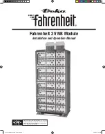
Fahrenheit 2V NB Module

Installation and Operation Manual

California

Proposition 65

Warning:

Batteries, battery posts, terminals and related accessories contain 

lead and lead compounds, and other chemicals known to the state 

of California to cause cancer and birth defects or other reproduc-

tive harm. 

Wash hands after handling. 

2600_Fahrenheit-2V-NB-mod_I&O.indd   1

2600_Fahrenheit-2V-NB-mod_I&O.indd   1

2/22/22   2:44 PM

2/22/22   2:44 PM

Содержание Fahrenheit 2V NB

Страница 1: ...ts terminals and related accessories contain lead and lead compounds and other chemicals known to the state of California to cause cancer and birth defects or other reproduc tive harm Wash hands after handling 2600_Fahrenheit 2V NB mod_I O indd 1 2600_Fahrenheit 2V NB mod_I O indd 1 2 22 22 2 44 PM 2 22 22 2 44 PM ...

Страница 2: ...1 Connector Assembly 13 Final Assembly 13 Safety Shield Assembly 14 System Operations Charge Voltage 15 Charge Current 15 Temperature Compensation 15 Cell Voltage 15 Rectifier Ripple Voltage 15 Record Keeping 15 Acceptance Testing 16 Maintenance Annual Inspection 16 Battery Cleaning 16 Capacity Testing 17 Cell Removal Procedure 17 Battery Maintenance Report 19 Appendix A Refresh Record Form 20 App...

Страница 3: ...g on cells Do not store un insulated tools in pockets or tool belt while working in vicinity of battery 4 Keep the top of the battery dry and clear of tools and other foreign objects 5 Provide adequate ventilation per IEEE standard 1187 and or local codes and follow recommended charging voltages 6 Extinguishing media Class ABC extinguisher Note CO2 may be used but not directly on the cells due to ...

Страница 4: ...uccessive recharges shall be performed every 6 months 78 F 26 C to 90 F 32 C Cell voltage readings shall be taken monthly Cells must be given a refresh charge within 3 months from date of receipt or if any cell voltage falls below 2 12 vpc whichever occurs first Successive refresh charges shall be performed every 3 months 5 Whenever a refresh charge is required it s important that all batteries to...

Страница 5: ... mounting base support from module pallet 2 Position base s consult included system layout diagram for required configuration Bases are required to be level prior to installing modules 3 Multiple stack systems should have a minimum of 4 00 between bases The additional spacing is for proper instal lation of modules 4 Anchor holes can be marked and drilled with bases in place All anchor holes in bas...

Страница 6: ...ding modules together 4 bolt assem blies and holding modules to pallet 4 bolt assemblies Hardware removed from module to module will be reused to attach modules to modules Hardware holding modules to pallet can be discarded 6 Module to Pallet Disassemble 6 Install modules onto bases using supplied lifting straps Consult below diagram for proper sling attachment and lifting Consult included system ...

Страница 7: ...grounding Consult Hardware Torque Requirements pg 2 for proper torque values 8 Bolt assemblies two per corner are required on the outside of the module to complete the base to module connection All 13 x 1 75 hardware should be checked for proper torque before proceeding Star washers are to be installed with teeth towards module to ensure proper grounding Consult Hardware Torque Requirements pg 5 f...

Страница 8: ...e outside of the module to complete the top plate to module connection All 13 x 1 75 hardware should be checked for proper torque before proceeding Consult Hardware Torque Requirements pg 5 for proper torque values Tier to Tier Retainer Bar Retainer Bar Installation 1 Tier to Tier Retainer Bar Installation Retainer bars are to be installed per the below detail All 3 8 16 x 1 25 hard ware should be...

Страница 9: ...ions Some installations may require the terminal plates to be in close proximity of each other It is recommended that the terminal plate assembly installations be completed prior to installing the inter cell connections This practice will reduce the risk of a possible electrical short from damaging the entire battery system TERMINAL ASSEMBLY Top Termination Consult system layout diagram for termin...

Страница 10: ...ements pg 5 for proper torque values 4 Install rubber caps over bolts Terminal Plate to be installed on battery posts as shown 6 Attach terminal plate to terminal plate bracket Note position of terminal plate Terminal Plate Bracket may have to be moved in order to be flush with the terminal plate 7 All hardware should be checked for proper torque before proceeding Consult Hardware Torque Requireme...

Страница 11: ...stic shields are of different lengths Longer shield to be installed on the front side of the terminal plate The shields should be even at the bottom making the front shield longer at the top Complete Assembly 2 Install plastic Side Terminal Bracket and re install safety shield bracket using bolts from previous step Use 3 8 16 x 1 50 bolt for the remaining bracket assembly Bolts should be installed...

Страница 12: ...et using 1 4 20 x 1 00 hardware Bolts should be installed loosely for future adjustments 6 After all parts are installed and alignment is confirmed torque all bolts Consult Hardware Torque Requirements pg 5 for proper torque values 8 Side Terminal Plate is designed to use up to 0 50 dia bolt and a maximum 1 75 centers and 1 188 min 2 hole lug Plate is capable of handling 4 runs of cable Lug Positi...

Страница 13: ...mbly Check Procedure 1 For future identification of all cells number individual cells in electrical connection sequence beginning with number one 1 at the positive end of the battery The last cell of the bat tery is located at the negative output terminal Note Following steps are to be followed with battery disconnected from any load or charge source 2 Read and record the voltages of the individua...

Страница 14: ...1 All Safety Shield Brackets should already be installed at this time Refer to Cell Installation Section for bracket installation 2 Safety Shields are designed with a keyhole type attachment Top Protection Shield Installation For side terminal assembly attach top protective cover to highest front shield 14 Bottom Overlap Top 3 One shield will cover one module or two tiers Starting with the bottom ...

Страница 15: ...ware Torque Requirements pg 2 for proper torque values Micro ohm readings should be taken across every connection Refer to meter manufacturer s instructions for proper placement of probes If any reading differs by more than 20 from its initial installation value re torque the connection consult Hardware Torque Requirements pg 5 for proper torque values If reading remains high clean contact surface...

Страница 16: ...ion portion of this manual 1 Other Maintenance Inspection intervals follow IEEE 1188 Battery Cleaning Batteries cabinets racks and modules should be cleaned with clear water or a mixture of baking soda and water or East Penn mfg supplied battery cleaner part 00321 Use clean water to remove baking soda residue Never use solvents to clean the battery 16 ACCEPTANCE TESTING Each cell should be at 100 ...

Страница 17: ...E 1 Before removing cell review Safety Precautions on pg 2 of this manual Contact East Penn Mfg Company Inc with specific questions or concerns 2 Remove one cell at a time 3 Confirm the lifting device is rated to handle the weight of one cell 4 All tools used to remove the cell shall be insulated to avoid metal contact with battery posts 5 Remove bolts from the retainer bar from the cell to be rep...

Страница 18: ...built up pressure while on open circuit Refer to step 5 for relieving the internal cell pressure 11 After cell has been installed into sleeve refer to Retainer Bar Installation section pg 8 SDS sheets can be obtained at www eastpennmanufacturing com 2600_Fahrenheit 2V NB mod_I O indd 18 2600_Fahrenheit 2V NB mod_I O indd 18 2 22 22 2 45 PM 2 22 22 2 45 PM ...

Страница 19: ... Excel Spreadsheet Consult your EPM Representative Readings should be taken at Installation and at least annually thereafter Battery Maintenance Report Company_ _ _______________________________________________________________ Service Date_______________________________________________________ Address_ _ ________________________________________________________________ Battery Dwg _________________...

Страница 20: ...Cell 12 Cell 13 Cell 14 Cell 15 Cell 16 Cell 17 Cell 18 Cell 19 Cell 20 Cell 21 Cell 22 Cell 23 Cell 24 ALL FIELDS TO THE RIGHT OF THE CELL NUMBER ABOVE MUST BE COMPLETED EPM ORDER NUMBER WILL APPEAR ON THE SHIPPING LABEL ON THE CARTON COVERING EACH PALLET OF CELLS TO ENSURE CONTINUATION OF WARRANTY SUBMIT FORMS TO East Penn Mfg Co Inc Reserve Power Division Product Support Warranty Dept reservepo...

Страница 21: ...21 BASE ANCHOR HOLE PATTERN Module Type A B 2 x 2 17 55 29 55 3 x 2 30 33 42 83 APPENDIX B 2600_Fahrenheit 2V NB mod_I O indd 21 2600_Fahrenheit 2V NB mod_I O indd 21 2 22 22 2 45 PM 2 22 22 2 45 PM ...

Страница 22: ...8 2 398 78 8 25 2 250 2 400 77 0 24 2 252 2 402 75 2 23 2 254 2 404 73 4 22 2 256 2 406 71 6 21 2 258 2 408 69 8 20 2 260 2 410 68 0 19 2 262 2 412 66 2 18 2 264 2 414 64 4 17 2 266 2 416 62 6 16 2 268 2 418 60 8 15 2 270 2 420 59 0 14 2 272 2 422 57 2 13 2 274 2 424 55 4 12 2 276 2 426 53 6 11 2 278 2 428 51 8 10 2 280 2 430 50 2mV per C 22 2600_Fahrenheit 2V NB mod_I O indd 22 2600_Fahrenheit 2V...

Страница 23: ...P a g e I n t e n t i o n a l l y B l a n k 2600_Fahrenheit 2V NB mod_I O indd 23 2600_Fahrenheit 2V NB mod_I O indd 23 2 22 22 2 45 PM 2 22 22 2 45 PM ...

Страница 24: ...y EPM Printed in U S A All data subject to change without notice No part of this document may be copied or reproduced elec tronically or mechanically without written permission from the company e mail reservepowersales dekabatteries com 2600_Fahrenheit 2V NB mod_I O indd 24 2600_Fahrenheit 2V NB mod_I O indd 24 2 22 22 2 45 PM 2 22 22 2 45 PM ...

Отзывы: