background image

6.2.4 Trip (fixed trip value)

The fixed trip value refers to tripping when the differential current is 100 % or more.

No.

Setting

Min. setting

Max. setting

Factory setting

1030

Diff. fixed limit trip

Selection display

-

-

-

1031

Diff. fixed limit trip

Delay

0.01 s

2.00 s

0.05 s

The relays (max. two) to be activated are chosen under Trip (curve 2).

6.2.5 Use of relay outputs

For each function (warning and trip), two relay outputs can be set (relay output A and B). For both of these,
any of the relays available (standard: relay 1-5) can be used.

Due to the fact that tripping the generator breaker is insufficient in case of a differential current failure, a total
generator shutdown must be carried out. Dependent on the AVR (Automatic Voltage Regulator) in question,
the AVR should also be tripped, ensuring that the generator voltage is removed immediately. It is suggested
to use for example relay output A to trip the breaker and relay output B to trip the AVR. Alternatively, if that is
not possible, to shut down the engine.

The reason for this shutdown is to stop the damaging current flow caused by the internal failure (differential
current).

If warning or trip messages are to be sent to an alarm system, it is suggested to use separate relays for each
warning or trip alarm sent to the alarm system. This enables the alarm system to identify the cause of alarm.

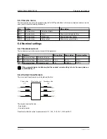
6.3 Other settings

6.3.1 Status LED

This setting enables/disables the use of yellow light in the protection LEDs. When set ON, the LEDs for I>>,
I> and Id will indicate an alarm status (yellow), if the alarm set point is exceeded, but the delay timer is still
running. If the timer has run out (the alarm is triggered), the LED will be red.

No.

Setting

First setting

Second setting

Factory setting

4300

Status info via LED

Selection display

-

-

-

4301

Status info via LED

Show status

OFF

ON

OFF

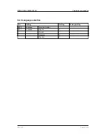
6.3.2 Auto acknowledgement of alarms

Automatic acknowledgement of alarms is activated by turning setting 4312 ON.

No.

Setting

Min. setting

Max. setting

Factory setting

4310

Auto acknowledge

Selection display

-

-

-

4311

Auto acknowledge

Delay

0.10 s

10.00 s

2.00 s

4312

Auto acknowledge

Enable

OFF

ON

OFF

MDR-2 DRH 4189340300 UK

Parameter programming

DEIF A/S

Page 23 of 26

Содержание Multi Differential Relay 2

Страница 1: ...Frisenborgvej 33 DK 7800 Skive Tel 45 9614 9614 Fax 45 9614 9615 info deif com www deif com 45 9614 9614 Fax 45 9614 9615 info deif com www deif com DESIGNER S REFERENCE HANDBOOK Multi Differential Re...

Страница 2: ...1 2 5 and 6 14 4 3 2 Slots 3 4 7 and 8 15 4 4 Terminal strip explanation 15 4 4 1 Slot 1 power supply and digital I O 16 4 4 2 Slot 7 AC current measurement 17 5 Wiring diagrams 5 1 Coupling and conn...

Страница 3: ...6 4 5 User password for programming via display 25 6 4 6 Language selection 26 MDR 2 DRH 4189340300 UK DEIF A S Page 3 of 26...

Страница 4: ...opened anyway the war ranty will be lost Disclaimer DEIF A S reserves the right to change any of the contents of this document without prior notice The English version of this document always contains...

Страница 5: ...also offers the user the information he needs in order to successfully set up the parameters needed in his specific application Please make sure to read this document before starting to work with the...

Страница 6: ...installation category over voltage category III 600 V pollution de gree 2 Galvanic separa tion Between AC current and other I Os 3250 V AC 50 Hz 1 min EMC CE According to EN 61000 1 2 3 4 IEC 255 3 Ma...

Страница 7: ...the generator motor and comparing these If there is a difference differential current a leak is detected The differential current detection takes place in each phase So the differential current detec...

Страница 8: ...xis Differential current Id in relation to nominal current In Y axis The lines marked UPPER LIMIT and LOWER LIMIT are the limits for the curves Max values are X1 500 Y1 45 Y2 95 Min values are X1 50 Y...

Страница 9: ...A 389A 389A PROT SETUP PROT Fail Comm The push buttons are INFO Displays the alarm list If no active alarms are present the list will be empty JUMP Enables the user to jump directly to a specific sett...

Страница 10: ...24 0 66 0 113 0 174 0 33 0 30 0 33 0 10 0 6x 4 5 Required space 220x115 mm Gasket outer 183x77 mm Screws for fastening 3 5 mm self cutting threads Max depth in display 9 mm MDR 2 DRH 4189340300 UK St...

Страница 11: ...2 Unit dimensions in mm inches Display 20 0 0 787 230 9 055 215 8 465 115 4 528 15 0 59 165 6 486 115 4 528 144 5 669 220 8 661 115 4 528 MDR 2 DRH 4189340300 UK Standard functions DEIF A S Page 11 of...

Страница 12: ...ment 98 109 Standard Slot 8 Not used 126 133 An overview of the terminals can be seen below The slots are positioned in the unit as follows seen from the top of the unit I I Id R1 R2 R3 R4 Sevice port...

Страница 13: ...deactivated relay output red by activated relay output NOTE I and I share the same LEDs I I and Id LEDs are turned off if the function is not chosen or inhibited I I and Id LEDs can indicate status ye...

Страница 14: ...4 3 Terminal strip overview 4 3 1 Slots 1 2 5 and 6 MDR 2 DRH 4189340300 UK Hardware DEIF A S Page 14 of 26...

Страница 15: ...nal strip explanation For the relay outputs the following terms will be used NO means Normally Open NC means Normally Closed Com means common terminal for the relay in question MDR 2 DRH 4189340300 UK...

Страница 16: ...nfigurable relay 9 Com 10 NC 11 NO Relay 3 250 V AC 8 A Configurable relay 12 Com 13 NC 14 NO Relay 4 250 V AC 8 A Configurable relay 15 Com 16 NC 17 NO Relay 5 250 V AC 8 A Configurable relay 18 Com...

Страница 17: ...ion 98 S1 k I 1L1 Primary side current measurements I1 99 S2 l 100 S1 k I 1L2 101 S2 l 102 S1 k I 1L3 103 S2 l 104 S1 k I 2L1 Secondary side current measurements I2 105 S2 l 106 S1 k I 2L2 107 S2 l 10...

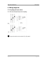
Страница 18: ...g diagrams 5 1 Coupling and connection 5 1 1 AC current measurements star coupling The ground connections can be connected to S1 or S2 as needed MDR 2 DRH 4189340300 UK Wiring diagrams DEIF A S Page 1...

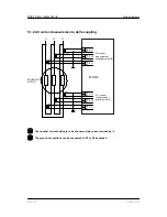
Страница 19: ...S1 107 106 I2 L2 S2 S1 105 104 I2 L1 S2 S1 103 102 I1 L3 S2 S1 101 100 I1 L2 S2 S1 99 98 I1 L1 S2 S1 S2 l S1 k S2 l S1 k S2 l S1 k S2 l S1 k S2 l S1 k GENERATOR MOTOR The nominal current setting is t...

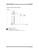
Страница 20: ...d outputs Alarms can be acknowledged by 1 Using the display 2 Activating the alarm acknowledge input 3 Auto acknowledge The use of this is selected in the setup menus MDR 2 DRH 4189340300 UK Wiring di...

Страница 21: ...rs Y1W Y2W DEL OA OB EN Is 0 0 0 1010 Diff Current W Setpoint 20 0 As it can be seen the cursor is placed under Y1W If SEL is pressed the setting of set point Y1W is entered password protected RESET S...

Страница 22: ...10 s 1014 Diff current warning Relay output A R0 none R5 relay 5 R3 relay 3 1015 Diff current warning Relay output B R0 none R5 relay 5 R5 relay 5 1016 Diff current warning Enable OFF ON ON 6 2 3 Trip...

Страница 23: ...he engine The reason for this shutdown is to stop the damaging current flow caused by the internal failure differential current If warning or trip messages are to be sent to an alarm system it is sugg...

Страница 24: ...No Setting Min setting Max setting Factory setting 4010 Nominal settings Selection display 4011 Nominal settings Nominal frequency 48 Hz 62 Hz 50 Hz 4012 Nominal settings Nominal current 1 A 10000 A 7...

Страница 25: ...me Minute 6 4 4 Power supply battery under voltage alarm No Setting Min setting Max setting Factory setting 4220 Battery low V Selection display 4221 Battery low V Set point 8 0 V 24 0 V 18 0 V 4222 B...

Страница 26: ...guage selection No Setting Setting Factory setting 4230 Language Selection display 4231 Language English 0 1 Deutsch 1 Fran ais 2 Espa ol 3 MDR 2 DRH 4189340300 UK Parameter programming DEIF A S Page...

Отзывы: