4. Hardware
4.1 Terminals and board slot positions
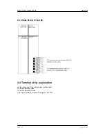
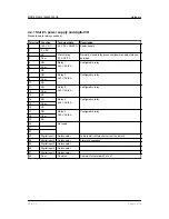
The Multi-line 2 housing is divided into board slot positions, some of which are standard (non-changeable)
and some intended for options. The MDR-2 unit is divided like this:
Slot
Slot type
Terminal
MDR-2
Slot #1
Power supply and digital I/O
1-28
Standard
Slot #2
Not used
29-36
Slot #3
Not used
37-64
Slot #4
Not used
65-72
Slot #5
Not used
84-89
Slot #6
Not used
90-97
Slot #7
AC current measurement
98-109
Standard
Slot #8
Not used
126-133
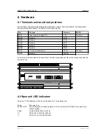
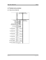
An overview of the terminals can be seen below. The slots are positioned in the unit as follows (seen from the
top of the unit):
I>> I>
Id
R1 R2 R3 R4
Sevice port
Display
1
2
3
4
5
6
7
8
4.2 Base unit LED indicators
There are 11 LED indicators on the front of the base unit. The indications are:
Power:
DC power is on
Self check OK:
The microprocessor watchdog status is OK. This relates to the "Status" relay output (nor-
mally energised)
Comm.:
Communication status: not used
I>>:
Option: short-circuit trip indication
I>:
Option: over-current trip indication
MDR-2 DRH 4189340300 UK
Hardware
DEIF A/S
Page 12 of 26


