


53
TYPE
00
TYPE
01
TYPE
02
TYPE
03
TYPE
04
OP
ERA
TING P
ARAMETERS
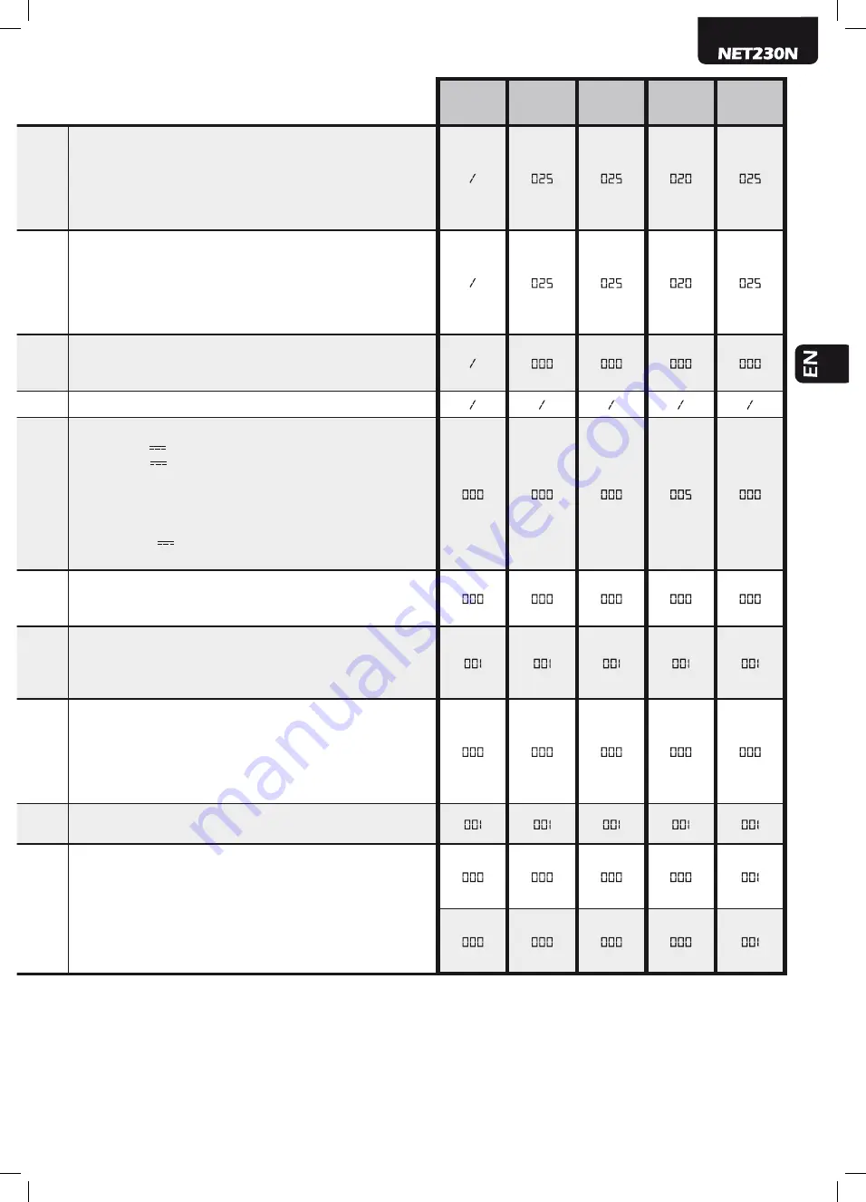
Adjustment of the opening stroke margin: it adjusts the duration of the last part of the stroke during which an
obstacle is interpreted as a stroke, blocking the motor without performing the inversion.
For motors with encoders, the set value indicates the number of revolutions of the rotor; while for motors
without encoder, the value is expressed in% of the maximum stroke.
Warning:
for motors without encoder, if P035 (duration slow-down while opening) is >10%, it forces the
stroke detection margin so that it’s the same than the slow-down.
1..................255 (motors with encoder)
0%…............100% (motors without encoder)
Adjustment of the closing stroke margin: it adjusts the duration of the last part of the stroke during which an
obstacle is interpreted as a stroke, blocking the motor without performing the inversion.
For motors with encoders, the set value indicates the number of revolutions of the rotor; while for motors
without encoder, the value is expressed in% of the maximum stroke.
Warning:
for motors without encoder, if P036 (duration slow-down while closing) is >10%, it forces the stroke
detection margin so that it’s the same than the slow-down.
1..................255 (motors with encoder)
0%…............100% (motors without encoder)
Operators force adjustment at stroke arrival - If=0, setting off (the force value on the stroke is calculated
automatically) - If≠0 (operators with encoder) it indicates the force value (expressed in% of the max value) set
in the last length - If≠0 (operators without encoder), max speed is activated during last length.
0%tot…...........................100%tot
Unused parameter
Electric-lock output operating: If=0 “boost” output for electric-lock art.110 power supply, If=1 24V output
controlled by the ELOCK_IN input as pulsed mode,If=2 24V output controlled by the ELOCK_IN input as
step-by-step mode, If=3 electro-brake output for not self-locking operators, If=4 24V output for electric-lock
power supply via an external relay, If=5 24V output for electro-magnets power supply for barriers, If>5 24V
output controlled by the ELOCK_IN input as temporized mode (the set value indicates the switch-off delay in
seconds).
• 000: “Boost” output for electric-lock art.110 power supply
• 001: “24V
pulse output max 5W
• 002: “24V
step-by-step output max 5W
• 003: “Electro-brake output for not self-locking operators
• 004: “Output for electric-lock power supply via an external
relay
• 005: “output for electro-magnets power supply for barriers
• >005: “24V
temporized output max 5W
(6sec………………255sec)
Run direction inversion: If=1 automatically reverses the outputs open/close of the operators and any opening/
closing limit switches inputs, avoiding having to manual change the wiring when installing the operator in an
inverted position.
• 000: “Standard installation”
• 001: “Inverted installation”
Multiplier operations-counter: Multiply the number of operations after which the total operations-counter will
be updated.
To view the values, refer to the section “Visualisation of inputs and operations-counter status”.
• 000: “x100
• 001: “x1000
• 002: “x10000
• 003: “x100000
Maintenance Operations-counter: if = 0 reset the counter and disables the intervention request , if>
0 indicates the number of operations (x 500) to be made before the control panel executes a 4 second
additional pre-flash to indicate the need of maintenance.
i.g.: If P065 = 050, operations number = 50x500 = 25000 operations
Warning:
Before you set a new value of the counter-manoeuvres maintenance, the same must be reset by
setting P065= 0 and only later P065 = “new value”.
• 000: “Request Maintenance disabled
• >000: “Number of operations (x 500) for required
maintenance
(1...................................255)
Selection of operating flashing light output: If=0 intermittent flashing light output; If=1 Fixed flashing light
output (for flashing lights with intermittent interior circuits).
• 000: “intermittent flashing light output
• 001: “fixed flashing light output
SAFETY 1
Operation of the SFT input: if = 0 safety edge always enabled, if = 1 safety edge enabled only
while closing, if = 2 safety edge enabled only while closing and before any movement, if = 3
safety edge enabled only when opening, if = 4 safety edge enabled only while opening and
before any movement; as for the obstacle detection with internal anti-crushing sensor, also the
activation of the inputs SFT1 and SFT2 causes the complete or partial reversal as set by P055
(duration of inversion on obstacles while opening, and P056 (duration of reversal on obstacle
while closing)
• 000: “safety edge always enabled
• 001: “safety edge enabled only while closing
• 002: “safety edge enabled only while closing and before any
movement
• 003: “safety edge enabled only when opening
• 004: “safety edge enabled only while opening and before any
movement
SAFETY 2
Содержание NET230N
Страница 30: ...28 ...
Страница 58: ...56 ...
Страница 86: ...84 ...
Страница 114: ...112 ...
Страница 142: ...140 ...
Страница 170: ...168 ...
Страница 198: ...196 ...
Страница 226: ...224 ...
Страница 227: ...225 ...