background image

Step 2

S4


(40cm)

 x2

S5


(40cm)

 x2

(57cm)

 x1

S6


Ø2.22cm

Ø3.81cm

Ø3.81cm

(Red)

(Red)

10

!

Please note 

the direction of the screw.

x2

x2

x3

S6

40cm

S5

40cm

S4

Содержание D-lite

Страница 1: ...ELECTRONIC DRUM SET USER MANUAL D lite...

Страница 2: ...instructional procedure for users to follow with ALWAYS FOLLOW THE INSTRUCTIONS AS DESCRIBED BELOW 1 Operation Warning Instruction for Prevention of Fire Electric Shock Physical Injury About Warning C...

Страница 3: ...hearing doctor Prevent letting any object like coins or pins or any liquid slip inside the machine 2 WARNING Please read the following instruction before operation Do not open or in any way modify the...

Страница 4: ...ghtning strike please remove the adapter from the socket 3 WARNING Should any of the following situations result please stop operation and remove the adapter from the socket and consult with your reta...

Страница 5: ...risk of hurting your Precautions Pleasereadthefollowingprecautionsasidefromthesafetyinstructions 4 Power Supply Do not share the power supply with other electronics that can produce cable statics for...

Страница 6: ...Sound Module MS310 x1 B1 Drum Stick 1 set x1 L1 Adapter x1 Accessories A2 Pad x5 B2 User Manual x1 L2 Sound Cable Black x4 L L Mono L 100 cm A3 Hi Hat Controller x1 A4 Bass Drum Controller x1 B3 Cable...

Страница 7: ...3 S4 S5 S6 S7 S8 20 cm 1 3 81cm 3 81cm 3 81cm 3 81cm 3 81cm 1 27cm 1 27cm 2 22cm Connectors C1 C2 C3 1 27 Pad Connector 3 81 2 22 Connector C4 1 27 2 22 Connector C5 C6 3 81 2 22 Connector x5 x2 x2 x2...

Страница 8: ...68 Expansion Connectors 7 C3 C1 C2...

Страница 9: ...123 89 8 C4 C5...

Страница 10: ...P1 P1 P1 P1 20cm S2 40cm S1 40cm S3 Step 1 S1 40cm x1 left S2 20cm x1 center S3 40cm x1 right P1 x4 3 81cm 3 81cm 3 81cm 9...

Страница 11: ...Step 2 S4 40cm x2 S5 40cm x2 57cm x1 S6 2 22cm 3 81cm 3 81cm Red Red 10 Please note the direction of the screw x2 x2 x3 S6 40cm S5 40cm S4...

Страница 12: ...Step 3 40cm x3 11 S7 40cm S7 40cm C2 S7...

Страница 13: ...Step 4 S7 S8 40 cm x1 20 cm left right x1 x2 P2 x2 P3 12 P2 P3 P2 S7 40cm S8 20cm P3...

Страница 14: ...Step 5 A2 x5 T1 x10 T2 x10 C2 x5 Depression Convex Below are examples of wrong assembly T1 T1 C2 T2 T2 A2 Use L2 100cm black cable connect NOTE 13...

Страница 15: ...the stand A1 x1 C6 x1 Position the Sound Module onto the Bar and fold the U Shape Plate upwards around the bar Secure the U Shape Plate to the back of the Sound Module with Screws Remove the protecti...

Страница 16: ...HI HAT CTRL BASS DRUM CTRL Sound Cable x4 L2 L3 x2 Connect the Sound Cables to the Drum Pads Pedals and Sound Module Mono cable one black line Stereo cable two black lines L2 L3 Red L4 Red L3 x1 HI HA...

Страница 17: ...Conecting the Pads TOM2 TOM3 BASS DRUM CYMBAL2 DC IN LINE IN MIDI OUT MENU HI HAT CTRL BASS DRUM CTRL HI HAT SNARE TOM1 CYMBAL1 Red Black optional headphone Amplifier optional optional 16 ADAPTER 5V1A...

Страница 18: ...ted to both Phone and Line Out MIDI OUT For connection of a sound input source like a portable music player a microphone other instruments or another sound source The sound is directed to both Phone a...

Страница 19: ...n the left side of the Sound Module s screen the picture of the Sound Module above displays Selection of ROCK Style When the Sound Module is turned on the setting will default to ROCK Style Available...

Страница 20: ...election of Sound Set 1 When the Sound Module is turned on the setting will default to Sound Set 1 Sound Set Press this button to Toggle Reverb On or Off The function of Reverb is to simulate the comp...

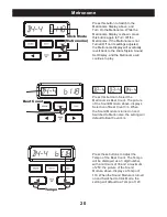
Страница 21: ...Press this button to Select the Metronome s Beat Count The picture of the Sound Module above displays Selection of Beat Count 3 4 When the Sound Module is turned on and Switched to Metronome the sett...

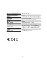
Страница 22: ...des Sensor 128 level ultra realistic velocity sensor Effect Reverb Metronome 30 250 BPM 3 kinds of beats Wiring Terminal o e r e t S 5 3 S E N O H P o e r e t S 5 3 N I E N I L MIDI OUT 5 pin DIN DC I...

Страница 23: ...H1 RIDE BELL BASS 1 1 2 3 4 1 2 3 4 1 2 3 4 1 2 3 4 1 2 3 4 1 2 3 1 2 1 2 22 1 2 3 4 5 6 7 8 ROCK 1 HI HAT SNARE TOM1 TOM2 TOM3 CRASH1 CRASH2 BASS 2 HI HAT SNARE TOM1 TOM2 TOM3 CRASH1 RIDE BELL BASS 3...

Страница 24: ...How to adjust hight Loose wing bolts Pull up or down the S5 pipe to adjust the height Fasten wing bolt STEP1 STEP2 STEP3 OR For more information please visit our website www ddrum com...

Отзывы: