background image

2

14

10

11

8

7

13

9

15

14

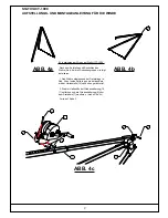
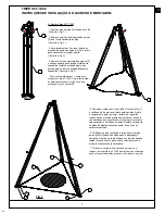
B)  Installieren der Winde am Stativ UCT-1000 

Nach dem Aufstellen und Ausrichten des 

Stativs (Abb. 4a) die Windenbaugruppe wie folgt 
installieren:

1. Das Stativ entsprechend der Darstellung in 

Abb. 4b auf seine Seite legen, wobei das Bein 
mit der Umlenkrolle[14] nach oben gerichtet ist.

2. Die drei Haltestifte der Windenhalterung[10, 

11] entfernen und die Windenhalterung[9] über 
dem Stativbein[7] montieren. ( 

siehe Abb. 4c

 )

Forts. auf Seite 3

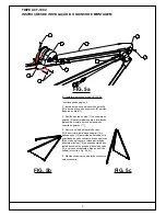
ABB. 4a

ABB. 4b

ABB. 4c

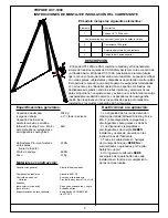
STATIV UCT-1000
AUFSTELLUNGS- UND MONTAGEANLEITUNG FÜR DIE WINDE

Содержание UCT-1000

Страница 1: ...6 REV B ADVANCED SYSTEM UCT 1000 Tripod 78 Model Number 8563159 EN795 1996 Class B 8 CE Type Test No 0086 BSI Product Services P O Box 6221 Kitemark Court Davy Avenue Milton Keynes MK1 9EP UK 9 CE Pro...

Страница 2: ......

Страница 3: ...1 operator setting up the T 1000 tripod it is easier to extend the legs by lying the tripod on the ground and proceeding with section A5 5 Position tripod over entry See Fig 3 and ensure structure is...

Страница 4: ...en set up leveled Fig 4a install the winch assembly as follows 1 Lay the tri pod on its side as shown in Fig 4b with leg containing pulley 14 up 2 Remove the three winch bracket retainer pins 10 11 an...

Страница 5: ...ion and install winch bracket retainer pin 11 5 Remove cable retainer pin 13 from top pulley assembly 14 and route cable 12 over pulley Extend sufficient cable from winch 8 to reach over pulley throug...

Страница 6: ...components at all adjustment points for tool less setup and adjustment General specifications Rated Capacity working load 204 Kgs 11 1 design factor Max Allowed Arresting Force M A F rating for retra...

Страница 7: ...g damaged or otherwise illegible warning stickers Any damaged missing or otherwise illegible stickers MUST BE replaced before using hoist If you are using Digital Series Winches with your hoist inspec...

Страница 8: ...ANNUALLY Date of Inspection d m y Inspected By T R I P O D LABELS DAMAGE CORROSION FASTENERS PULLEYS ROLLER ANCHOR POINTS WINCH BRACKET SRL s BRACKET WELDS OTHER COMMENTS Failure to comply and follow...

Страница 9: ...s pieds du tr pied en tendant celui ci sur le sol et en suivant la section A5 5 Positionner le tr pied sur l entr e voir Fig 3 et s assurer que la structure est niveau R gler la longueur du ou des pie...

Страница 10: ...les instructions ci dessous 1 Placer le tr pied sur le c t comme indiqu sur la Fig 4b avec le pied comprenant la poulie 14 orient e vers le haut 2 Retirer les trois broches de retenue du support de t...

Страница 11: ...Retirer la broche de retenue du c ble 13 de l assemblage de la poulie sup rieure 14 et acheminer le c ble 12 sur la poulie Tirer une longueur suffisante de c ble partir du treuil 8 pour atteindre la...

Страница 12: ...indiqu e charge d utilisation 204 kg avec un facteur de conception de 11 1 Classification de la force d arr t maximale autoris e Maximum Arrest Force M A F des dispositifs r tractables ou des amortis...

Страница 13: ...ntes endommag es ou illisibles Les tiquettes endommag es manquantes ou illisibles DOIVENT TRE remplac es avant d utiliser l l vateur Si vous utilisez des treuils de s rie num rique avec votre l vateur...

Страница 14: ...MAGES CORROSION FIXATIONS POULIES ROULEAU POINT D ANCRAGE SUPPORT DU TREUIL SUPPORT DE LIGNE DE VIE AUTOR TRACTABLE SOUDURES AUTRE COMMENTAIRES LE NON RESPECT DES PROC DURES D INSPECTION INDIQU ES DAN...

Страница 15: ...A5 e appoggiando il treppiede a terra 5 Posizionare il treppiede sopra il punto di accesso Fig 3 e verificare che la struttura sia stabile e in piano Per regolare la lunghezza delle gambe rimuovere un...

Страница 16: ...1 Mettere il treppiede di lato come mostrato nella Fig 4b con la gamba con la puleggia 14 rivolta verso l alto 2 Rimuovere i tre fermi della puleggia del verricello 10 11 e installare la staffa del v...

Страница 17: ...ere il fermo del cavo 13 dal gruppo della puleggia superiore 14 e dirigere il cavo 12 sopra la puleggia Estrarre una quantit di cavo sufficiente dal verricello 8 per arrivare sopra la puleggia attrave...

Страница 18: ...co operativo 204 kg con fattore di progetto 11 1 La forza massima di arresto Maximum Arrest Force M A F consentita per i dispositivi retrattili o i dissipatori di sollecitazioni non deve superare gli...

Страница 19: ...ti mancanti o illeggibili DEVONO essere sostituiti prima dell uso del dispositivo di sollevamento Se per il sollevamento si utilizzano verricelli digitali controllare verricello e cavo come indicato n...

Страница 20: ...ontrollato da T R E P P I E D E ETICHETTE DANNI CORROSIONE DISPOSITIVI DI FISSAGGIO PULEGGE RULLO PUNTI DI ANCORAGGIO STAFFA DEL VERRICELLO STAFFA DEL CAVO SRL SALDATURE ALTRO COMMENTI SE NON SI RISPE...

Страница 21: ...legen und dann mit Abschnitt A5 fortfahren 5 Das Stativ ber dem Einstieg positionieren siehe Abb 3 und darauf achten dass die Vorrichtung eben steht Die L nge der Beine nach Bedarf durch Entnahme des...

Страница 22: ...1 Das Stativ entsprechend der Darstellung in Abb 4b auf seine Seite legen wobei das Bein mit der Umlenkrolle 14 nach oben gerichtet ist 2 Die drei Haltestifte der Windenhalterung 10 11 entfernen und d...

Страница 23: ...en 5 Den Sicherungsseil Haltestift 13 aus der oberen Umlenkrollenbaugruppe 14 ziehen und das Seil 12 ber die Umlenkrolle f hren Ausreichend Seil von der Winde 8 ziehen damit es ber die Umlenkrolle dur...

Страница 24: ...werkzeugfreie Aufstellung und Einrichtung Allgemeine technische Daten Nenntragf higkeit Arbeitslast 204 kg bei einem Traglastfaktor von 11 1 Maximal zul ssige Bremskraft MAF f r R ckzugger te oder St...

Страница 25: ...rweitig nicht lesbare Warnaufkleber Besch digte fehlende oder anderweitig unlesbare Aufkleber M SSEN vor der Verwendung des Hebeger ts ersetzt werden Wenn Sie f r Ihr Hebezeug Winden der Digital Serie...

Страница 26: ...ETIKETTEN BESCH DIGUNGEN KORROSION BEFESTIGUNGSMITTEL UMLENKROLLEN ROLLE ANKERSPITZEN WINDENHALTERUNG SRL HALTERUNG SCHWEISSN HTE SONSTIGES BEMERKUNGEN DIE NICHTEINHALTUNG DER IN DIESEM HANDBUCH ANGEG...

Страница 27: ...r pode en el suelo y continuando con la secci n A5 5 Coloque el tr pode sobre la entrada vea la Fig 3 y aseg rese de que la estructura est nivelada Ajuste el largo de las patas seg n se requiera retir...

Страница 28: ...oye el tr pode en uno de sus lados tal como se muestra en la Fig 4b con la pata que contiene la polea 14 hacia arriba 2 Retire los tres pasadores de retenci n del soporte del cabrestante 10 y 11 e ins...

Страница 29: ...ire el pasador de retenci n del cable 13 de la parte superior del conjunto de la polea 14 y pase el cable 12 sobre la polea Deje pasar suficiente cable desde el cabrestante 8 como para llegar 5 pies p...

Страница 30: ...dad clasificada carga de trabajo 204 Kg a 11 1 factor de dise o Capacidad de fuerza de detenci n m xima permitida Allowed Arresting Force M A F para dispositivos replegables o amortiguadores para golp...

Страница 31: ...encia o si est n da adas o son ilegibles Las etiquetas que est n da adas ausentes o ilegibles DEBEN reemplazarse antes de utilizar el sistema de izado Si utiliza cabrestantes Digital Series con el sis...

Страница 32: ...nspeccionado por T R P O D E ETIQUETAS DA O CORROSI N BRIDAS POLEAS RODILLO PUNTOS DE ANCLAJE SOPORTE DEL CABRESTANTE SOPORTE DE SRL SOLDADURAS OTROS COMENTARIOS SI NO CUMPLE Y SIGUE LOS PROCEDIMIENTO...

Страница 33: ...c o A5 5 Posicione o trip sobre a entrada Consulte a Fig 3 e certifique se de que a estrutura est nivelada Ajuste o comprimento da s perna s conforme requerido removendo os pinos de ajuste das pernas...

Страница 34: ...orma 1 Apoie o trip na sua parte lateral conforme apresentado na Fig 4b com a perna que cont m a roldana 14 para cima 2 Remova os tr s pinos de bloqueio do suporte do guincho 10 11 e instale o suporte...

Страница 35: ...bloqueio do cabo 13 da estrutura da roldana superior 14 e passe o cabo 12 pela roldana Estenda uma quantidade de cabo suficiente desde o guincho 8 de modo a alcan ar a roldana atrav s da estrutura pr...

Страница 36: ...cidade nominal volume de trabalho 204 Kgs num factor de constru o de 11 1 ndice de for a m xima de paragem permitida para dispositivos retract is ou amortecedores de choque 6kN Ensaio de carga Guincho...

Страница 37: ...ou ileg veis de qualquer outra forma Quaisquer autocolantes de advert ncia em falta danificados ou ileg veis de qualquer outra forma T M DE SER substitu dos antes da utiliza o do elemento elevat rio...

Страница 38: ...P ETIQUETAS DANO CORROS O DISPOSITIVOS DE FIXA O ROLDANAS CILINDRO PONTOS DE ANCORAGEM SUPORTE DO GUINCHO SUPORTE DA CORDA DE SEGURAN A AUTO RETR CTIL SOLDADURAS OUTRO COMENT RIOS O N O CUMPRIMENTO E...

Страница 39: ...or slechts 1 bediener is het makkelijker om de poten uit te schuiven als de driepoot op de grond ligt en dan verder te gaan met sectie A5 5 Plaats de driepoot over de ingang Zie afb 3 en zorg dat de c...

Страница 40: ...opgesteld en waterpas staat afb 4a installeert u als volgt de lierconstructie 1 Leg de driepoot op zijn kant zoals afgebeeld in afb 4b met de poot die de katrol 14 bevat naar boven 2 Verwijder de dri...

Страница 41: ...ugel vergrendelingspin 11 in de lierbeugel 5 Verwijder de kabelvergrendelingspin 13 uit de bovenzijde van de katrolconstructie 14 en leid de kabel 12 over de katrol Trek voldoende kabel uit de lier 8...

Страница 42: ...ezet met pinnen die snel losgemaakt kunnen worden voor instellen en aanpassen zonder gereedschap Algemene specificaties Toegestane capaciteit werkbelasting 204 kg Bij 11 1 designfactor Max toegestane...

Страница 43: ...en draaien Inspecteer alle apparatuur op ontbrekende beschadigde of op andere wijze onleesbare waarschuwingsstickers Alle beschadigde ontbrekende of op andere wijze onleesbare stickers MOETEN worden v...

Страница 44: ...KS Inspectiedatum d m j Ge nspecteerd door D R I E P O O T LABELS SCHADE CORROSIE BEVESTIGINGSMATERIALEN KATROLLEN ROLLER VERANKERINGSPUNTEN LIERBEUGEL BEUGEL SRL s LASSEN OVERIG OPMERKINGEN Het niet...

Страница 45: ...1 2 3 1 4 1 2 3 4...

Страница 46: ...ausschlie lich f r den Gebrauch von pers nlicher Schutzausr stung entworfen wurde Anschlageinrichtungen d rfen nur mit CE gekennzeichneten Absturzsicherungssystemen verwendet werden Beim Gebrauch dies...

Страница 47: ...chgef hrt Keine von CAPITAL SAFETY schriftlich oder m ndlich an H ndler Vorstandsmitglieder F hrungskr fte Agenten oder Angestellte bergegebenen Informationen oder Hinweise ergeben jegliche andere ode...

Страница 48: ...EMEA Europe Middle East Africa Le Broc Center Z I 1 re Avenue 5600 M B P 15 06511 Carros Le Broc Cedex France Phone 33 4 97 10 00 10 Fax 33 4 93 08 79 70 information capitalsafety com CSG Australia N...

Отзывы: