background image

Qu-Bot, A Quickly Programmable Robot User’s Manual 

Page 

37

 of 

52


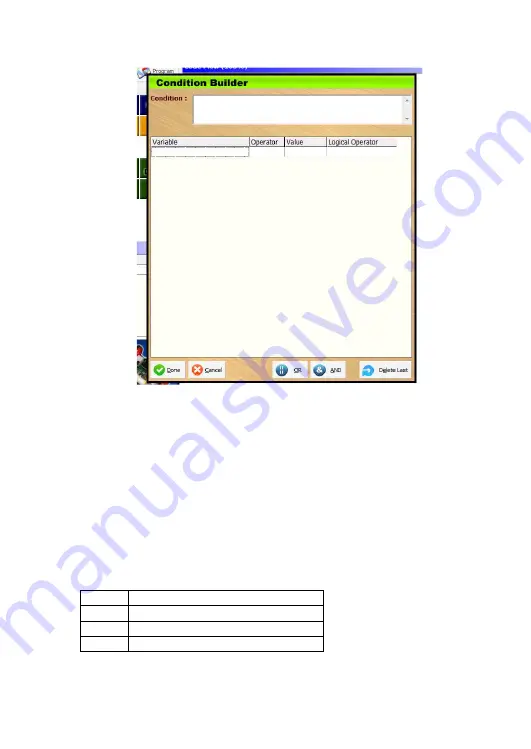
6.1.1.1. Operand1 

There are four columns in the condition builder block. First of all click on Variable 
blank  box  to  see  drop  down  menu.  Here  you  will  see  all  sensor  input  variables. 
Also there are general purpose variables available which can be compared through 
this block. Check section 7.2. 
Eight  variables  represent  3X  line  sensors,  3X  Obstacle  sensors  and  2X  Motor 
counter (Encoder) Values.  
LDR Value variable represents ambient light value. 
Switch1, Switch2 & Switch3 variables represent switch press status. 
All the above variables fetch latest input from the system when they are used. 
IR Input & UART Input variables also can be compared but they will need different 
structure. Please check section 7.3.1. 

6.1.1.2. Operator 

Second column in condition builder is used to select operator. 

== 

Checks equality 

!= 

Checks inequality 

Less Than 

Greater Than 

Содержание Qu-Bot

Страница 1: ... when robot is not in use for a long time Do not store the robot for long time when the battery is discharged This will drastically decrease the life of battery Keep the kit away from small children There are many small parts which can create problem if swallowed Battery and motor connectors are polarized Do not try to force insert them in wrong direction This will damage the robot permanently Do ...

Страница 2: ...e Please contact info qu bot com for inquiries The Qu Bot Robot kit connects to the PC via USB cable included and is programmable through an easy to use QBVLab drag and drop modular icon based software program After the program sequences have been uploaded into the robot via USB it can be controlled by remote control PC or can behave according to the user defined parameters The Qu Bot runs on Li i...

Страница 3: ...atibility with all PC s and Laptops 8 Easy Icon based visual programming for beginners sample programs included 9 Onboard li ion rechargeable battery which can run Qu Bot for more than 3 hours 10 Battery charged through AC charger Input Modules Onboard 1 3X Proximity Sensors 2 3X Line Follower Sensors 3 2X Motor Counter Sensors 4 1X Remote Control Receiver Sensor 5 1X Ambient Light Sensor 6 3X Gen...

Страница 4: ...1X Li ion Rechargeable Battery 3 7V 1 4Ah with protection circuit 3 2X Geared DC motors 4 2X Mounting Clamps for motor 5 2X Wheels 6 1X Castor 7 1X USB Cable 8 1X Remote Control 9 1X Battery Charger Adaptor 10 1X CD with all software and documentation l 11 All screws nuts and cable ties Tools required assembling Qu Bot 1 Screw driver 2 Pliers or spanner ...

Страница 5: ... to set attributes of any component block 26 3 2 3 Programming Qu Bot 27 3 2 4 Deleting block from code flow window 27 4 Programming in Qu Bot Visual LAB Output Blocks 28 4 1 Lighting LED s 28 4 1 1 Characteristics of LED Block 28 4 1 2 Changing Attributes 28 4 1 3 LED On Off Sequence 28 4 2 Ringing buzzer 29 4 2 1 Characteristics of Buzzer Block 29 4 2 2 Changing Attributes 29 4 2 3 Ringing Buzze...

Страница 6: ... ELSE IF Condition ELSE ENDIF blocks 36 6 1 1 Structure 36 6 1 2 Condition Building Operands and Operators 36 6 1 3 Function of IF ELSE IF ELSE ENDIF 38 6 1 4 Glow LED s as per switch press status 39 6 2 Other IF blocks 39 6 3 Nested IF ELSE sample 40 7 Programming in Qu Bot Visual LAB Operational Blocks 41 7 1 Data Types 41 7 2 Variables in Qu Bot 41 7 3 Variable Block 41 7 3 1 Special Cases 41 7...

Страница 7: ...rogrammable Robot User s Manual Page 7 of 52 1 Identification of components Assembling 1 1 Assembling Qu Bot Qu Bot Kit contents out of the box Castor motor clamps cable ties and different screws and nuts included in kit ...

Страница 8: ... 3 long screws in the castor wheels 3 holes keeping plastic washers in between as shown in picture Step 2 Insert castor wheel with screws to the Qu Bot PCB allocating the 3 holes After inserting place 3 more plastic washers on the top and lock the castor wheel to PCB with nuts ...

Страница 9: ...t as shown above Cut the extra portion of cable ties with paper cutter or nipper Step 4 Place the clamp on the 2 holes on the back part of robot Clamp it with PCB with 2 small screws and nuts The placement is very critical If the clamp is not parallel to PCB edge the motor will not be straight and robot will now move in a straight line A good idea is to align the clamp to PCB track while assembly ...

Страница 10: ...f 52 Step 5 After securing a castor battery and 2 clamps the robot now looks as above from back side Step 6 Now attach motor to the clamp as shown above Put the screws inside the holes in motors through clamps and tighten nuts on them as shown in above picture ...

Страница 11: ...ake care while plugging in the connectors All the connectors are polarized so they cannot be inserted wrongly but still do not try to force them in different configuration This may damage the board permanently Step 8 Now place 2 wheels over the motor shaft press them properly and secure them with a metal washer and screw as shown in picture ...

Страница 12: ...charge led will glow the charging is complete When Qu Bot is connected to PC using USB it gets powered up irrespective of the state of power switch When AC charger is connected the Qu Bot will be disconnected from battery and charger but if USB cable is connected to PC the robot will be working and battery will get charged through AC power Charging battery though USB may take up to 12 15 hours Dis...

Страница 13: ...Qu Bot A Quickly Programmable Robot User s Manual Page 13 of 52 1 2 Identification of parts on assembled Qu Bot ...

Страница 14: ...On Off Switch If Pressed power on 12 USB Connector Connects to USB of PC through USB cable Qu Bot also gets powered and charged 13 IR Remote Sensor Receives signals from IR remote 14 Li ion Battery Battery which powers up Qu Bot Remove Battery connector when not in use 15 LCD Header Connects to 16X2 LCD 16 Line follower sensors Also called as downward Sensors 17 SW1 SW2 SW3 Input Switches 18 Reset...

Страница 15: ...f PC you need to install driver for USB on your PC Qu Bot is compatible with most windows versions In this manual all screenshots are taken from Windows 7 Ultimate operating system however Qu Bot is tested on most of the windows versions successfully After starting the setup the above window appears Qu Bot uses PL2303 chip for USB communication This is the driver for the same ...

Страница 16: ...Qu Bot A Quickly Programmable Robot User s Manual Page 16 of 52 Press next to continue On License agreement page click I accept and click next ...

Страница 17: ...he USB cable from Qu Bot should now automatically detect the device and give connect device sound It will also show balloon from the task bar as shown in above picture In case of any problem to verify that driver is installed correctly you can check Control Panel System Device Manager Ports There should be a device called Prolific USB to Serial Comm Port Port number ...

Страница 18: ...on In Qu Bot CD there is a setup file for Qu Bot Visual Lab software The file name is QBVLabSetup exe Run this file to install QBVLab software On the welcome screen click next to install software On ready to install page it shows location where the files will be installed Click next to start setup ...

Страница 19: ...Robot User s Manual Page 19 of 52 Within few seconds the software gets installed Now the software is installed Press finish to exit installer The QBVLab icon now appears on desktop as well as start menu Run it to start the software ...

Страница 20: ...ools View and Help 2 Quick menu bar Contains New Load Save and Program options 3 Components window Contains operational output and conditional blocks 4 Attribute explorer Indicates component block properties 5 Zoom out Zoom in Shown only if further zoom in or zoom out is possible 6 Collapse all and expand all buttons Expands and collapse all branches 7 Code flow window Space for programming Qu Bot...

Страница 21: ... 2 Menu Bar 3 1 2 1 File 3 1 2 1 1 New Code Ctrl N Creates a new blank file Click the New button on quick menu bar or File New Code 3 1 2 1 2 Open Ctrl O Opens a previously saved file Click Open button on quick menu bar or File Open Then select QBF file and click open ...

Страница 22: ...need of adding QBF extension 3 1 2 1 4 Save As Shift F2 Similar to Save Saves file in different name Click File Save As 3 1 2 1 5 Exit Ctrl X Exit from QBVLab 3 1 2 2 Tools 3 1 2 2 1 Load Program Ctrl L Program written in code flow is transferred to Qu Bot via USB Cable Please connect USB Cable before programming 3 1 2 2 2 Serial Terminal Ctrl T Opens Serial Terminal window from which you can send...

Страница 23: ...2 3 1 2 3 1 Zoom In F7 Makes All icons smaller in size 3 1 2 3 2 Zoom Out F8 Makes All icons smaller in size 3 1 2 3 3 Expand All F11 Expands All Branches 3 1 2 3 4 Collapse All F12 Collapse all Branches Zoom In Zoom Out 3 1 2 4 Help 3 1 2 4 1 Contents Browse Help ...

Страница 24: ... Start End logic blocks are already added to the code flow which indicates start and end of Qu Bot Program These blocks can t be dragged from component window 1 Output blocks Yellow 2 Operational blocks Blue 3 Conditional blocks Green 4 Loop blocks Red 5 Start and End blocks Purple 3 1 3 1 Output blocks Yellow Controls Buzzer on off and toggle Controls LED1 2 and 3 on off and toggle Displays Text ...

Страница 25: ...crement counter variable 3 1 3 3 Conditional blocks Green 1 Split code flow depending upon the condition If condition is true execute IF part and then go to step5 2 Check for next ELSEIF or ELSE block 3 If ELSEIF is encountered check condition If condition is true execute ELSEIF part and then go to step5 Else go to step2 4 If ELSE is encountered execute else part 5 Execute code flow below ENDIF In...

Страница 26: ...rom component window Drag it to the position you want in the code flow release click on mouse to drop the component block If you have dragged the component block to the correct place in code flow window then the component block will be added in the code flow at that position Try to move LED block in the code flow 3 2 2 How to set attributes of any component block All component blocks can be set to...

Страница 27: ...complete on status bar and USB Status symbol Red you can check your Qu Bot Do not disconnect USB cable while USB status is green LED1 will be ON Also you will hear three short beeps from buzzer which indicates END of program Programming status indication 3 2 4 Deleting block from code flow window To delete any block and right click on the block and select delete from the menu All sub Items that ar...

Страница 28: ...ck on the LED block in code flow to see attributes Select Output Left click on value block to see drop down menu For Each LED there are three options Total options available are LED1 ON LED1 OFF LED2 ON LED2 OFF LED3 ON LED3 OFF TOGGLE LED1 TOGGLE LED2 and TOGGLE LED3 4 1 3 LED On Off Sequence Arrange the block and set attributes as shown in the figure Check section 7 5 for setting delay block att...

Страница 29: ...n downloaded to Qu Bot Buzzer will be on for 1 second Buzzer will be off for 1 second Buzzer will beep thrice indicating end of program 4 3 Writing to LCD 4 3 1 Characteristics of LCD Block LCD Block controls 16X2 Liquid Crystal Display on Qu Bot LCD is detachable from Qu Bot hence you can select whether to use LCD or not from Start Block attribute Set LCD Init attribute to Yes to use LCD If you h...

Страница 30: ...t Variable Output Text Active only when LCD Output Type value is Text The text value is written to LCD at current cursor position Output Variable Active only when LCD Output Type value is Variable The variable value is written to LCD at current cursor position 4 3 3 Display Text on LCD Arrange the blocks and set attributes as shown in the figure The program will execute as below when downloaded to...

Страница 31: ...LEFT MOTOR FORWARD LEFT MOTOR BACKWARD RIGHT MOTOR FORWARD RIGHT MOTOR BACKWARD STOP LEFT MOTOR STOP and RIGHT MOTOR STOP Speed Speed of motor can be selected from drop down menu ranging from 0 to 10 10 is maximum speed 4 4 3 Moving Qu Bot in a circle Arrange the blocks and set attributes as shown in the figure The program will execute as below when downloaded to Qu Bot Left motor will move at hal...

Страница 32: ...RT Output Type Selects output type between TEXT VARIABLE and NEWLINE Output Text Send Text output to PC Active only if UART Output Type is Text Output Variable Send Variable Value as output to PC Active only if UART Output Type is Variable 4 5 3 Display Text on Serial Terminal Arrange the blocks and set attributes as shown in the figure The program will execute as below when downloaded to Qu Bot T...

Страница 33: ... will print YOU ARE USING UART SAMPLE CODES and NEWLINE Buzzer will beep thrice indicating end of program 4 5 4 Using Serial Terminal to check output of above program Select Tools Serial terminal to start serial terminal Select proper Baud Rate Click Clear Console and then click on Connect to Qu Bot You will see above output on console ...

Страница 34: ...all when code flow will encounter WHILE 1 block The Qu Bot will save the position of the next block Then it will execute the program normally and LED1 will be on and off for 100mS When code flow encounters ENDWHILE block it will return to the position saved by WHILE 1 block Hence the same sequence will be repeated endlessly 5 2 WHILE Condition Conditional loop This section is just to introduce thi...

Страница 35: ...loop is just like a infinite WHILE 1 loop Hence it will blink LED1 Once you press Switch1 the code flow will move to WHILE Condition block within max 100ms and check condition If you have put 5 seconds of delay instead of 100mS and you press and release switch1 within delay time the condition won t be checked and the loop won t break Hence the LED1 will continue to blink Try and check result yours...

Страница 36: ...de flow window will look like left image If you do not want ELSE block you can right click on the block and select delete See 3 2 4 Then your code flow will look as shown in center image If you delete ELSE from any IF structure you will not be able to restore it ELSE IF Condition can be put between IF and ELSE Block If there is no ELSE block it can be put anywhere in between IF Condition and ENDIF...

Страница 37: ...n 7 2 Eight variables represent 3X line sensors 3X Obstacle sensors and 2X Motor counter Encoder Values LDR Value variable represents ambient light value Switch1 Switch2 Switch3 variables represent switch press status All the above variables fetch latest input from the system when they are used IR Input UART Input variables also can be compared but they will need different structure Please check s...

Страница 38: ...conditions LDR Value 100 Ambient light intensity Less than 100 0 99 BOTTOM CENTER 1 Line follower center censor is on Switch1 1 Switch1 not pressed LEFT MOTOR COUNT 1000 Left motor has moved more than 1000 counts forward FRONT LEFT 1 Obstacle left sensor senses obstacle Switch1 1 AND Switch2 1 AND Switch3 1 All three switches are pressed Switch1 1 OR Switch2 1 OR Switch3 1 Any switch is pressed LD...

Страница 39: ...used within an infinite loop From first sight it looks that both the programs are same But there is functional difference Find out what is the difference Hint Press more than one switch and release only switch 6 2 Other IF blocks Right side program in section 6 1 4 can also be written through IF Switch block as shown in above figure Also it will be much faster In all IF blocks you can add ELSE IF ...

Страница 40: ...F ELSE sample IF block inside IF or ELSE Block generates nested IFELSE Above right side image shows three levels of nesting and the same program should clarify your all doubt of IF ELSE structure Press all three switches release them in different sequences and check LED output ...

Страница 41: ...le in section 7 2 and UART Input and IR Input Left click on the variable block in code flow and check attribute explorer Variables can be initialized like blow 1 Variable1 Constant 2 Variable1 Variable2 Select Variable1 from variable name dropdown box Select Value type from Variable or Constant If you have selected Variable choose variable from the list or else type constant value Once the variabl...

Страница 42: ...bove variable block once you will get UART Input W and FIFO e are using UART If used again UART Input e FIFO are using UART Please check simple program and output of the same on UART console 7 3 1 2 IR Input IR Remote Sends signals every 114ms Hence we cannot have data instantaneously like other sensors which provide data in 1 2uS Hence the program flow waits for IR signal for around 200ms Input i...

Страница 43: ...ions 1 Variable Variable1 or Constant 2 Variable Variable1 or Variable2 The above image will multiply INT17 84 and store result in LONG6 variable LONG6 INT17 84 Also you can right the same statement by initializing any character variable to 84 using variable block and then operate as LONG6 INT17 CHAR30 Constant value must be between 0 255 7 5 Delay Block This block is used to generate delay in seq...

Страница 44: ...ite Timer Value in the box The above attribute explorer shows the delay value is set to 100 Milliseconds 7 6 Counter Block This block increments or decrements CNT1 to CNT10 variables This block is normally used in loops for counting purpose Choose Counter number from the drop down box and select operation to be performed As per above image CNT5 will be decremented ...

Страница 45: ...ble Robot User s Manual Page 45 of 52 8 Application Programs 8 1 Bugler alarm This sample code shows the basic application of sensors and buzzer When any of the front sensors senses an object the buzzer goes on for infinite time ...

Страница 46: ...ow status of robot The robot starts moving when switch 1 is pressed because there is a while conditional loop on top By default robot keeps moving forward at speed 7 When front sensor senses obstacle the robot moves backwards for 500 ms and takes a left turn for 200 ms at speed 10 When left or right sensor senses an obstacle the robot stops opposite side motor to take turn in reverse direction ...

Страница 47: ...table surface it takes actions accordingly By default the robot moves forward If the bottom center sensor doesn t detect table surface moves out of edge robot moves backward and takes a turn If bottom left or right sensor moves out of edge the robot takes turn in opposite direction Be careful when using robot with this code programmed Sometimes there is a chance of robot falling down Keep alertnes...

Страница 48: ...lution it moves forward to 208 182 mm distance periphery of wheel So at each count we get distance of 208 182 16 13 mm This is also the accuracy which we get when the robot moves on motor count If we want robot to move forward to 1 meter robot has to go forward until it gets 77 1000 13 motor counts on motor counter So this is how it works When switch1 is pressed robot starts moving forward The rig...

Страница 49: ...eft motor Right motor is stopped So the robot takes a long right turn When it gets the line under the bottom sensor it continues to take right turn until it crosses it completely After a small delay of 50ms the left motor stops and right motor starts moving so robot takes a left turn Again it continues taking the left turn until it crosses the line After a 50 ms delay the procedure repeats because...

Страница 50: ...line the value is 0 This means the robot is on the line It will move forward in this condition If the bottom center sensor goes off either left or right sensor will encounter the line If left sensor senses the line left motor stops and right motor runs at full speed so robot takes a left turn and comes back on line If Right sensor encounters line right motor stops and left goes on full speed so ro...

Страница 51: ...t the code is from 1 to 127 There are 4 big arrow keys on the center of remote This code uses them for moving robot Any key of the remote can be used to create any action on robot The 4 arrow keys have IR codes of 32 Up 33 Down 17 Left 16 Right The key codes of other keys can be recognized by printing the IR Input variable to LCD or serial Terminal on PC For manual control robot there is a simple ...

Страница 52: ...unication like HyperTerminal and bray s terminal The QBVLab software itself includes a terminal In advanced applications it s possible to control Qu Bot from the inputs of mouse keyboard webcam internet or any other source available on PC However this needs a high level of programming and hardware knowledge on PC but this sample code gives a demo on how to move Qu Bot on commands taken from keyboa...

Отзывы: