INSTALLATION INSTRUCTIONS
R
−
410A Split System Heat Pumps
14
428 01 1703 01
Specifications subject to change without notice.
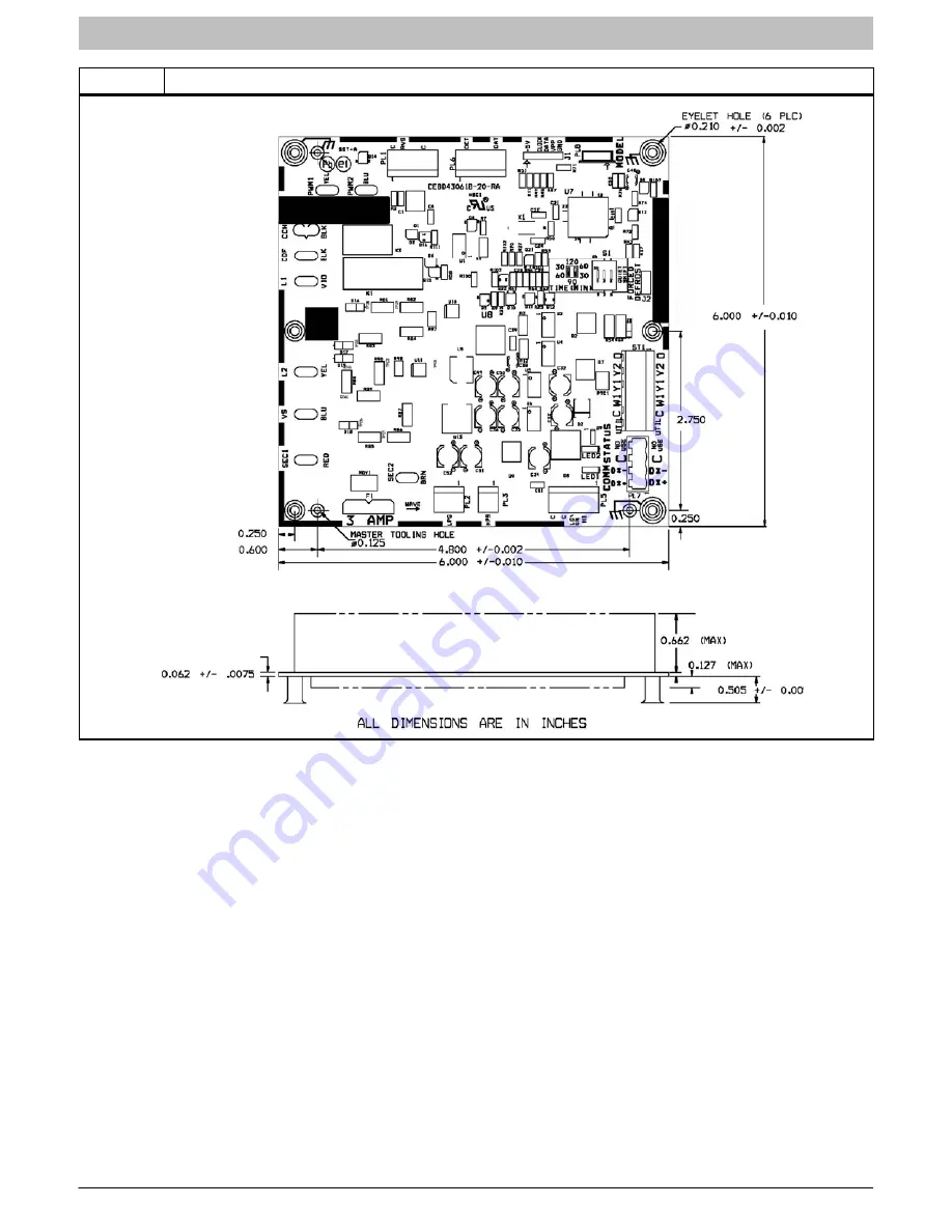
Figure 14
Two
Stage Control Board
Страница 1: ...hanced installation reliability or operation Signal Words in Manuals The signal word WARNING is used throughout this manual in the following manner The signal word CAUTION is used throughout this manu...
Страница 2: ...d refrigerant tubing from joists and studs with a rigid wire or strap which comes in direct contact with tubing See Fig 1 8 Ensure that tubing insulation is pliable and completely surrounds vapor tube...
Страница 3: ...ctions from kit for installation CAUTION UNIT DAMAGE HAZARD Failure to follow this caution may result in equipment damage or improper operation To prevent damage to the unit ensure that it is located...
Страница 4: ...ft 6 09 m vertical differential refer to Long Line Applications Guideline Table 2 Refrigerant Connections and Recommended Liquid and Vapor Tube Diameters In UNIT SIZE LIQUID RATED VAPOR up to 80 ft 2...
Страница 5: ...E HAZARD Failure to follow this caution may result in equipment damage or improper operation Service valves must be wrapped in a heat sinking material such as a wet cloth while brazing CAUTION UNIT DA...
Страница 6: ...d Power Wires Remove access panel to gain access to unit wiring Extend wires from disconnect through power wiring hole provided and into unit control box WARNING ELECTRICAL SHOCK HAZARD Failure to fol...
Страница 7: ...ment size See Observer Wall Control Installation Instructions and indoor specification sheet for available adjustments Airflow Setup with Non Communicating Furnace or Fan Coil Two stage compressor ope...
Страница 8: ...age 1 Heat Stage 3 Heat Cool Stage 2 Fan 24 VAC Hot Dehumidify 24 VAC Comm Humidify RVS Heating Outdoor G O R W1 Y Y2 C Y1 W2 H O Y1 Y2 C W1 Two Stage Heat Pump Remove J2 Jumper For Heat Staging s s H...
Страница 9: ...age of cooling Y1 and O are powered on and with second stage of cooling Y1 Y2 and O are on For these systems with first stage of heating Y1 is on and for second stage of heating Y1 and Y2 are on When...
Страница 10: ...There is no delay between staging from low to high and from high to low capacity The compressor will change from low to high and from high to low capacity on the fly to meet the demand DEFROST This c...
Страница 11: ...th Accessory Liquid Solenoid Using a Non Communicating Thermostat The liquid solenoid is connected to the Y1 and C terminal connections The liquid solenoid closes in the compressor off mode to prevent...
Страница 12: ...te fault code Compressor Thermal Cutout If the control senses the compressor voltage after start up and is then absent for 10 consecutive seconds while cooling demand exists the thermal protector is o...
Страница 13: ...ure If the outdoor ambient or coil thermistor should fail the control will flash the appropriate fault code see Table 6 IMPORTANT Outdoor air thermistor and coil thermistor are factory mounted in the...
Страница 14: ...INSTALLATION INSTRUCTIONS R 410A Split System Heat Pumps 14 428 01 1703 01 Specifications subject to change without notice Figure 14 Two Stage Control Board...
Страница 15: ...ault 55 Coil sensor not reading or out of range Ohm out sensor and check wiring Thermistors out of range 56 Improper relationship between coil sensor and outdoor air sensor Ohm out sensors and check w...
Страница 16: ...10A as with other HFC refrigerants is only compatible with POE oils Vacuum pumps will not remove moisture from oil Do not use liquid line filter driers with rated working pressures less than 600 psig...