DAVIS 6322C Скачать руководство пользователя страница 23

21

Anemometer Siting Guidelines

• For best results, place the anemometer at least 7' (2.1 m) above surrounding 

obstructions such as trees or buildings that obstruct wind flow.

• If mounting on a roof, mount the anemometer at least 7' (2.1 m) above the roof 

apex. (When using a Davis Mounting Tripod, install the anemometer at the very 
top of the pole).

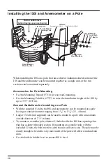
• If mounting the ISS and the anemometer together, such as on a pole or a wooden 

post, mount the anemometer so it is at least 12'' (0.3 m) above the top of the rain 
collector cone for best results.

• The standard for meteorological and aviation applications is to place the 

anemometer 33' (10 m) above the ground. Seek professional help for this type of 
installation.

• The standard for 

agricultural applications 

is to place the anemometer 6' (2 m) 

above the ground. This is important for evapotranspiration (ET) calculations.

Note: 

For roof mounting, and ease of installation, we recommend using the optional mounting 
tripod (#7716). For other installations, use the Mounting Pole Kit (#7717).

Note: 

For more detailed siting suggestions, see Application Note #30: Reporting Quality 
Observations to NOAA on http://www.davisnet.com/resources.

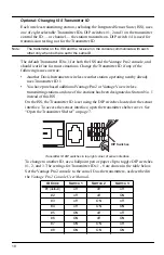
Optional: Cable Length Considerations

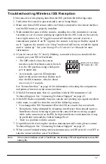
• All Vantage Pro2 stations include a 

40' (12 m) cable to go between the 
ISS and the anemometer. This can 
be extended up to 540' (165 m) 
using optional extension cables 
purchased from Davis Instruments. 
If most of the anemometer cable 
length is unused, the coiled cable 
length can be stowed once the 
anemometer and ISS have been 
installed on a site. You can secure 
the cable to the pole using the 
shorter cable ties. Use the longer 
cable tie to secure the coil by 
running it through the holes on the 
rain collector shelf.
Keep the anemometer cable coiled 
if possible during the ISS and 
anemometer assembly so that it is 
easily stowed once installation is 
complete.

• The Cabled Vantage Pro2 includes a 100' (30 m) cable to go between the console 

and the ISS. This can be extended up to 1000' (300 m) using optional cables.

Anemometer
Cable

Shorter
Cable Tie

Longer
Cable Tie

Содержание 6322C

Страница 1: ...Integrated Sensor Suite USER MANUAL Davis Instruments 3465 Diablo Avenue Hayward CA 94545 2778 U S A 510 732 9229 www davisnet com R For Vantage Pro2 Vantage Pro2 GroWeather and Vantage Pro2 Plus...

Страница 2: ...the receiving antenna Increase the separation between the equipment and receiver Connect the equipment into an outlet on a circuit different from that to which the receiver is connected Consult the de...

Страница 3: ...e and the transmitter It collects outside weather data from the ISS sensors and then transmits the data to your Vantage Pro2 console Vantage Vue console wireless only Weather Envoy Envoy8X wireless on...

Страница 4: ...be included in the package that are not shown here Components Anemometer Vane Wind Cups Anemometer Cable 40 12 2 m Anemometer Base Anemometer Arm Control Head Console Cable 100 30 m Cabled ISS Only De...

Страница 5: ...nd Daytime Fan Aspirated Shield VANTAGE PRO2 with 24 Hour Fan Aspirated Shield 24 Hour Fan Aspirated Radiation Shield VANTAGE PRO2 PLUS and GroWeather with 24 Hour Fan Aspirated Shield UV Sensor Vanta...

Страница 6: ...ead screwdriver electric if possible Adjustable wrench or 7 16 wrench Compass or local area map Ballpoint pen or paper clip or other small pointed object Drill and 3 16 5 mm drill bit if using lag bol...

Страница 7: ...ing parts to prepare the anemometer Anemometer arm wind vane and cable already attached Anemometer base Wind cups Allen wrench 0 05 4 machine screw 4 tooth lock washer 4 hex nut Attach the Anemometer...

Страница 8: ...1 Push the wind cups up onto the anemometer s stainless steel shaft sliding them up the shaft as far as possible 2 Use the Allen wrench provided to firmly tighten the set screw on the side of the win...

Страница 9: ...e side of the shelter The box cover can be easily removed from the box when the alignment indicator on the cover is lined up with the alignment indicator on the box 5 Pull the cover off the box being...

Страница 10: ...as the rain collector 1 Remove the protective cap from the RJ jack on the anemometer cable 2 Pull the foam insert out of cable access port and set the foam insert aside 3 Insert the anemometer cable...

Страница 11: ...e off the ISS base Tip When new the cone fits tightly in the base and may require extra pressure to remove Steady the ISS base between your knees when removing the cone 2 Carefully cut and remove the...

Страница 12: ...ed in your hardware kit Note Inserting the metric measurement adapter converts the rain collector to take measurements in 0 2 mm increments for each tip of the spoons The console must be configured to...

Страница 13: ...adapter 6 Insert the metric adapter and magnet between the arms of the spoons with the top solid side of the metric adapter facing up Next Steps See Cabled ISS Assembly on page 12 for assembling a cab...

Страница 14: ...n the sensor interface firmly insert either end of the 4 conductor cable into the modular receptacle labeled COMM 4 If you haven t powered up the console yet refer to the installation instructions in...

Страница 15: ...then press RAIN YR for current ultraviolet readings or press 2ND then press RAIN DAY for solar radiation readings The UV reading displays in the center of the console The solar reading displays in th...

Страница 16: ...into the ISS jack on the console Make sure that the cable is firmly plugged into the jack labeled COMM on the sensor interface Verify that all sensor cables are firmly plugged in A green LED indicato...

Страница 17: ...in communicating automatically when power is applied Note If there is another Davis weather station within range of your console or Vantage Connect you should change the Transmitter ID Remember to use...

Страница 18: ...eiving data the outside relative humidity HUM OUT reading should be displayed on the console 6 If the ISS contains a UV sensor and or solar radiation sensor press 2ND and then press RAIN YR for curren...

Страница 19: ...es each time the ISS transmits which is about once every 2 5 seconds See Sensor Interface on page 46 for information on locating the components and points of interest on the sensor interface 5 If the...

Страница 20: ...already uses Transmitter ID 1 You have purchased additional Vantage Pro2 or Vantage Vue wireless transmitting stations and one of the stations has been designated as Station No 1 instead of this ISS...

Страница 21: ...allowable only if one stations has only leaf wetness and one has only soil moisture sensors For example a network can either have both a Leaf Wetness Temperature station and a Soil Moisture Temperatur...

Страница 22: ...urally landscaped area that drains well when it rains For areas with average maximum yearly snow depths over 3 0 9 m mount the ISS 2 0 6 m above this depth Never install the ISS where it will be direc...

Страница 23: ...tional mounting tripod 7716 For other installations use the Mounting Pole Kit 7717 Note For more detailed siting suggestions see Application Note 30 Reporting Quality Observations to NOAA on http www...

Страница 24: ...visions heaters or air conditioners Transmission between wireless units may be obscured by something unidentifiable or by some obstacle that can t be worked around For best results orient the ISS ante...

Страница 25: ...more information on the diagnostic screens It s a good idea to test the console s reception anywhere that you might want to use or mount it now or in the future Take your time If you aren t picking up...

Страница 26: ...nd anemometer together or separately on a pole Use the lag screws to install them separately on a flat vertical surface The anemometer comes with a 40 12 m cable for flexibility in positioning the sys...

Страница 27: ...ole using cable ties or by wrapping tape around both the cables and the pole Place clips or ties every 3 5 1 1 6 m Mounting clips cable ties or additional hardware not included with your station can b...

Страница 28: ...8 54 mm apart Use a carpenter s level to ensure the holes are level Use the metal backing plate as a guide when marking the holes 2 Remove the rain collector cone if it is installed on the ISS mountin...

Страница 29: ...screws through the flat washers and the holes in the anemometer mounting base into the post 3 Tighten the lag screws using an adjustable wrench or 7 16 wrench Note If your anemometer arm cannot be mou...

Страница 30: ...o 13 4 32 44mm Larger U bolts not supplied can be used to mount to a pole with a maximum outside diameter of 21 2 64mm To mount on a smaller pole obtain a U bolt that fits the ISS base openings but th...

Страница 31: ...at its round end fits in the top groove on the rain collector mounting base The groove is right above two large holes 2 While holding the mounting base of the rain collector against the pole place the...

Страница 32: ...r north in the Southern Hemisphere Not needed for cabled systems 4 Tighten the hex nuts using an adjustable wrench or 7 16 wrench Option 3 Installing Anemometer Only 1 While holding the mounting base...

Страница 33: ...d droppings can clog the rain collector To use the bird spikes insert one spike into each socket around the rim of the cone The sockets are tapered push firmly or tap lightly with a hammer for a more...

Страница 34: ...alling the solar or UV sensors separately see the Solar Radiation and UV Sensor installation manual for more information Start the 24 Hour Fan If your ISS has a 24 Hour Fan Aspirated Radiation Shield...

Страница 35: ...ll cables are compatible with your Vantage Pro2 system To be sure they will work order Davis extension cables from your dealer or directly from Davis Instruments Be aware that the maximum measurable w...

Страница 36: ...shield Try not to touch the small white diffusers on top of the sensors Oil from skin reduces their sensitivity If you are concerned that you have touched the diffusers at any time clean with a soft c...

Страница 37: ...p hum sensor assembly which is located inside the radiation shield Maintaining a Standard Passive Radiation Shield 1 Remove the rain collector cone 2 Open the transmitter shelter and unplug the temp h...

Страница 38: ...ield Tools and supplies needed Medium Phillips head screwdriver and a small Phillips head screwdriver if you are also replacing the batteries Adjustable wrench Soft damp cloth Soft brush such as a too...

Страница 39: ...nt and routing so you can replace it correctly 6 Unscrew the three threaded spacers holding the solar bracket and radiation shield together and lift off the solar bracket 7 Remove the two cap plates R...

Страница 40: ...radiation shield Wipe it clean as well as up into the interior of the radiation shield Replace the screen 14 Replace the temperature humidity sensor It fits one way into the slots on the side Route t...

Страница 41: ...h the screws in the rain collector base Note that cables should exit from the radiation shield toward the mounting pole or post Screw the screws into the threaded spacers 18 Route the temperature humi...

Страница 42: ...tor cone 2 Open the transmitter shelter and unplug the temp humidity cable and the fan power cable from the sensor interface 3 Using a Phillips head screwdriver loosen the three screws connecting the...

Страница 43: ...ace the fan motor and batteries in the 24 Hour Fan Aspirated Radiation Shields use product no 7758B Standard Motor Kit for Fan Aspirated Radiation Shield with Batteries To replace the motor in a Dayti...

Страница 44: ...e connections account for a large portion of potential problems Connections should be firmly seated in receptacles and plugged in straight To check for a faulty connection try jiggling the cable while...

Страница 45: ...wind cups don t spin or don t spin as fast as they should The anemometer may be located where wind is blocked by something or there may be friction interfering with the cups rotation Remove the wind c...

Страница 46: ...Update Intervals Transmitter ID Dependent Wind speed 2 5 to 3 seconds Wind direction 2 5 to 3 seconds Accumulated rainfall 20 to 24 seconds Rain rate 20 to 24 seconds Outside temperature 10 to 12 seco...

Страница 47: ......

Страница 48: ...ect to change without notice Davis Instruments Quality Management System is ISO 9001 certified 3465 Diablo Avenue Hayward CA 94545 2778 U S A 510 732 9229 Fax 510 732 9188 E mail info davisnet com www...

Отзывы: