Attaching Cable Strain Reliefs
Page 3
A
TTACHING
C
ABLE
S
TRAIN
R
ELIEFS
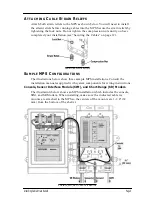
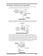
Attach both strain reliefs to the MPS as shown below. You will need to install
the strain reliefs before running cables into the MPS. Secure the strain reliefs by
tightening the lock nuts. Do not tighten the compression nuts until you have
completed your installation (see “Securing the Cables” on page 12).
I
NSTALLING
S
TRAIN
R
ELIEFS
S
AMPLE
MPS C
ONFIGURATIONS
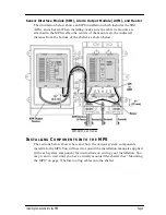
The illustrations below show three sample MPS installations. Consult the
installation manuals supplied with system components for wiring instructions.
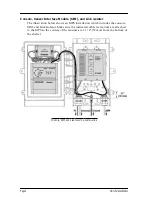
Console, Sensor Interface Module (SIM), and Short-Range (SR) Modem
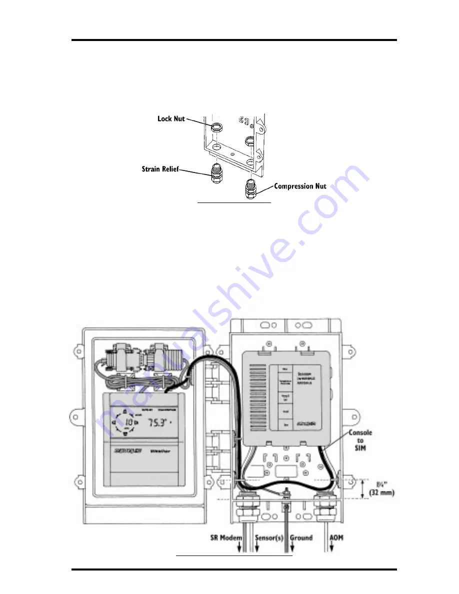
The illustration below shows an MPS installation which includes the console,
SIM, and SR Modem. When installing, make sure the indicated cable tie
mounts are attached to the MPS so the centers of the mounts are 1-1/4" (32
mm) from the bottom of the shelter.
C
ONSOLE
, SIM, SR M
ODEM
I
NSTALLATION


