10/31/2016
DAVID DAVID 5 Manual
http://www.david3d.com/en/support/david5/printversion
19/37
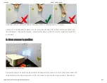
Ideal live camera image for calibration
Check the camera image: In the areas where the waves are visible, the red intensity curves must not reach
the blue lines. If the object to be scanned is considerably darker than the white glass calibration panels,
the sine waves will now be overdriven. Correct this by temporarily reducing the
Projector Brightness
slider
in the software. The camera image for calibration should look similar like shown in figure obove.
6. Calibrate
Click
Calibrate
to calibrate the entire scanner. In this step, the software first measures the position,
orientation, focal length and distortion characteristics of the camera. Then, a pattern sequence is projected
in order to measure the same optical characteristics of the projector. If texturing is not turned off, finally a
white balance is performed. After successful calibration, a checkerboard pattern is projected, the corners of
which should fall exactly into the calibration points.
The scanner is now calibrated. This refers to the position and rotation of camera and projector according to
each other, as well as focusing and brightness settings. You can move, tilt and rotate the scanner as a
whole, and you can close the DAVID software and restart it without losing the calibration. You can also
change the value of
Projector Brightness
to adjust the brightness (red sine curves) to the respective


