10/31/2016
DAVID DAVID 5 Manual
http://www.david3d.com/en/support/david5/printversion
16/37
An advantage of the modular design of the DAVID 5 scanners is that it can be adjusted to scan a wide
range of objects sizes. Therefore, a calibration (measurement of the scanner hardware in the software) is
necessary so that the software can then obtain precise and undistorted 3D data at the correct scale. For
this purpose, a 90° pair of glass calibration panels is used as a reference object, whose dimensions are
precisely known.
1. Setup calibration panel
Setting up the glass calibration panels
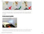
Set up the calibration corner. You will need both 90° fixing brackets and the glass calibration panels. Put
one fixing bracket flat on the used surface (e.g. a table). Insert the glass calibration panels in the fixing
bracket. Finally, attach the second fixing bracket on the glass calibration panels.
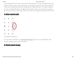
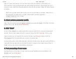
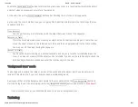
For starters, the pattern should be folded inwards. Advanced users can avoid undesired reflections
with an outwardly folded pattern if necessary. Fix the glass calibration panels using the two fixing
brackets to exactly 90°.
2. Select pattern scale


