6
DVLD User Manual
5) Connect one end of the USB cable to the USB connector on the USB-RS485LD.
6) Connect the other end of the USB cable to the USB connector located on the rear panel of
the Davicom unit.
7) Connect to the Davicom unit using the DavLink software.
8) In the DavLink software, go to the configuration menu by clicking on the configuration icon
or select Unit from the main menu and Unit Configuration from the dropdown list.
9) Click on Devices. Next, click on the Davicom Expansions tab and finally click on the DVLD
tab.
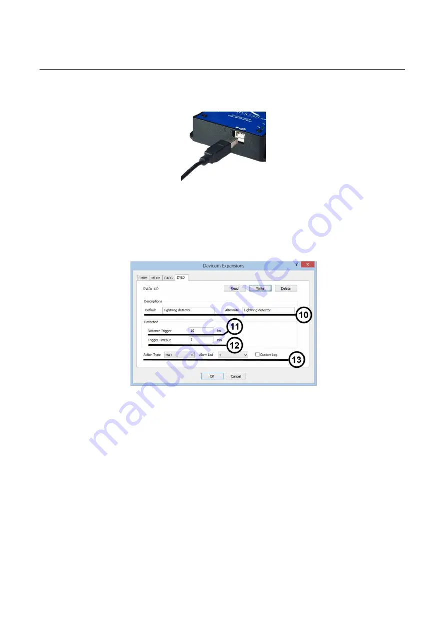
10) If necessary, change the Default and Alternate (language) text descriptions.
11) Set the Distance Trigger parameter to any value between 5 km and 40 km. Lightning
activity outside this range will not be logged. Default value is 10 km.
12) Set the Trigger Timeout (additional delay before returning to normal conditions after the
last detected lightning activity—see section 6 below). Default value is 10 min.
13) Select the Action Type, the Alarm List number and check the Custom log box if the alarms
need to be logged.
14) Click OK and confirm the changes.
15) To display the information provided by the DVLD, you must create workspaces in DavLink
by using the 2 flags/variables that contain the DVLD’s information.
16) The first flag of interest is the 1LD flag. It is used to indicate the connection state of the
DVLD. The 1LD flag must be passed through a Virtual Logic Gate (VLG) in order for its
value to be displayed. It is not directly useable as an input for a display “object” in DavLink.
The figure below shows how to create a VLG for this purpose. This VLG is also set to give


