5
DVLD User Manual
3
Background
Davicom’s DVLD Lightning Detector is an add-on sensor for Davicom’s line of Intelligent Remote
Monitoring and Control Systems. It is based on a circuit that is designed to automatically detect
the approach of lightning storms by analyzing and recognizing the electromagnetic signature of
lightning strikes. In addition, the circuit contains a hardwired averaging and distance estimation
algorithm that provides the distance to the leading edge of the storm.
Together, the DVLD and Davicom units can be used to detect approaching lightning storms, to
send alarms when the storm reaches a certain minimum distance, to de-activate or disconnect
sensitive equipment and even to log the storm’s track.
4
Installation and initial configuration
ATTENTION: You are strongly advised to set up the DVLD and test it in your particular
environment for several weeks before actually controlling site equipment from its
readings. Although we have put every effort into ensuring that the unit will perform
flawlessly in various electromagnetic environments, it is not impossible that certain
installations contain defective or electrically noisy components that could affect the
DVLD’s operation.
The DVLD comes in 2 parts:
•
The outdoor detector (DVLD-1)
•
The indoor USB converter (USB-RS485LD)
1) You must install the DVLD outdoors and secure it to a wall or post using the PVC clamp
provided with the unit (or Tie-Wraps). The DVLD must be installed vertically so that the
cable exits from the bottom of the unit. We recommend that the sensor be installed at a
height of at least 6’ from the ground and at a distance of at least 12” from a metallic
structure. We do not recommend installation directly on the transmission tower.
For safety and optimum detection performance, make sure that the Davicom
unit’s chassis is properly grounded.
2) Run the DVLD cable from the probe to the interior of the building. Avoid passing the cable
near sources of electrical noise such as fluorescent lights and ballasts.
3) Secure the USB-RS485LD to the equipment rack or panel.
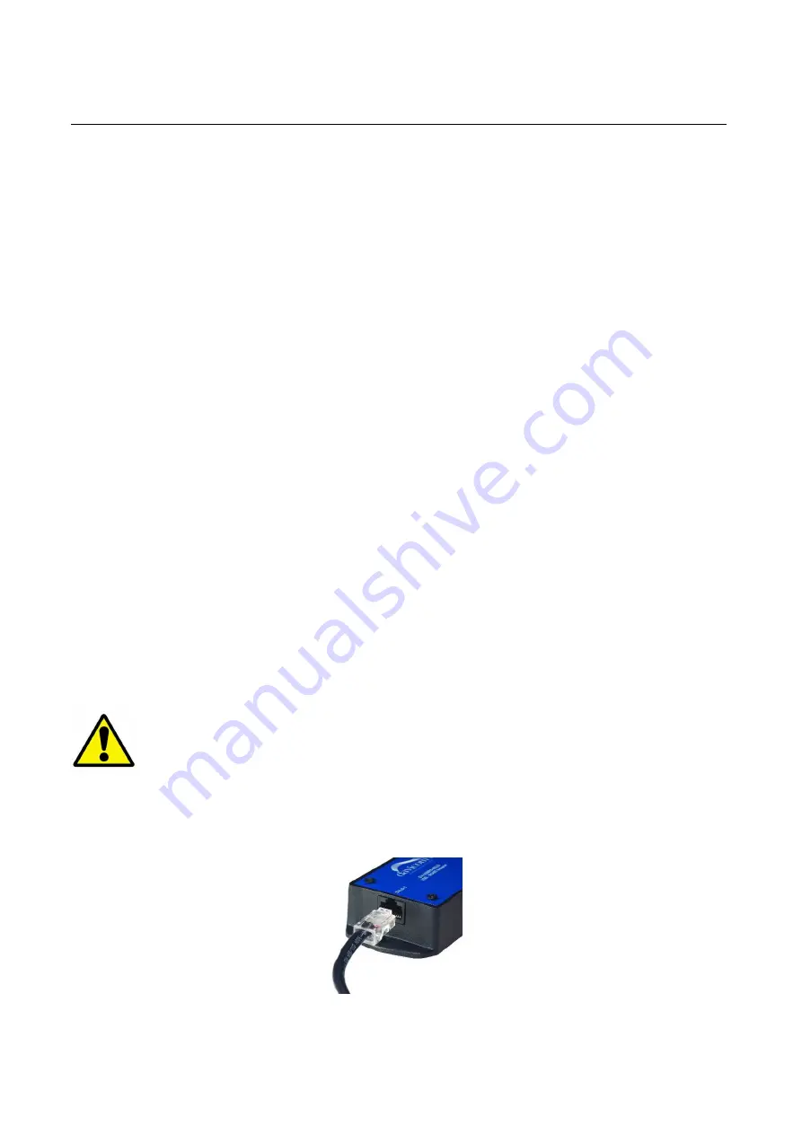
4) Connect the DVLD cable to the connector labeled DVLD-1 on the USB-RS485LD.


