Davey HS Series Скачать руководство пользователя страница 6

 6

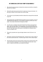
HS SERIES MULTISTAGE PUMP DISASSEMBLY

1.

Disconnect the power supply and release the pump pressure before removing the
pump to do any repairs.

2.

Remove the eight casing screws with a 5mm allen key turning anti-clockwise.  Sit
the pump on the fan cowl for easier removal of the screws.

3.

You may have to put a flat blade screwdriver between the casing and the back plate
to pry it off.

4.

The first stage body should lift off and it should also have an oring with it.  If it is not
still attached to the stage body, check inside the casing to see if it is stuck to the
inside.  If so remove it and check for flat spots and tears.

5.

You will now see a stainless steel nut that holds the rest of the pump assembly in
place.  This is removed with a 17mm ring spanner.  You will need to sit the pump
horizontally and remove the fan cowl.  Place a flat blade screwdriver into the slot in
the rotor, hold it tight and give the spanner a sharp tap with a softhead mallet to
loosen the impeller screw.

6.

Remove the impellers wear rings and stage bodies and check for wear or rub
marks.

7.

Remove the mechanical seal and casing oring.  Check for wear or signs of heat on
the seal faces and rubber boot.  Check the oring for tears or flat or pinched spots.

8.

The back plate can be removed by inserting a small punch through the holes in the
motor end shield and tapping it off.  Remove the slinger from the shaft.  Check,
clean or replace all parts before you reassemble the pump.

Содержание HS Series

Страница 1: ...ffice and Manufacturing 6 Lakeview Drive Scoresby Australia 3179 Ph 61397309222 Fax 61 3 9753 4100 Website www davey com au CustomerServiceCentre Ph 1300367866 Fax 1300369119 E mail sales davey com au...

Страница 2: ...tion the Davey pump motor is fitted with an automatic reset thermal overload constant tripping of this overload indicates a problem e g low voltage at pump excessive temperature above 50 C in pump enc...

Страница 3: ...r and put the mechanical seal on using a little water on the rubber boot and pushing it down over the shaft until the seal faces meet The carbon seal face should be in contact with the ceramic wear fa...

Страница 4: ...d wear ring One more stage body and another impeller in the case of a four stage pump or a spacer in place of the impel ler if it is a three stage pump The impeller spacer or the impeller should be si...

Страница 5: ...g and screw the non return valve cartridge into the suction port in a clockwise rotation using non specified tools eg a screwdriver handle a pair of pliers a large coin or a flat blade 20mm wide 14 Yo...

Страница 6: ...You will now see a stainless steel nut that holds the rest of the pump assembly in place This is removed with a 17mm ring spanner You will need to sit the pump horizontally and remove the fan cowl Pl...

Страница 7: ...the following a Power failure b Blown fuse c Motor overload tripped d Motor windings faulty 3 Motor thermal overload tripping May be caused by one or more of the following a Low voltage supply b Motor...

Страница 8: ...oilet cistern hot water system or stock troughs allowing unit to overflow d Pressure tank not retaining air pressure or air change too high pressure switch model only 6 Pump not switching off or takin...

Отзывы: