DT1400 xx xx
20170920-V0
15
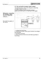
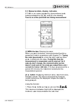
5.5. Connecting the analogue output (option)
The following figure shows the wiring plan, connecting
analogue output in case of
active (DT1400 RL2 IA, DT1400 RL2 IA PS) or
passive (DT1400 RL2 IP, DT1400 RL2 IP PS) output:
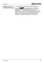
Wiring plan, connecting
the analogue output
(see also “Application
example”)
Be careful the polarity of
the cables.
1. Loosen terminal screws.
2. Insert the wire ends into the open terminals according to
the wiring plan.
3. Screw the terminal in.
4. Check the hold of the wires in terminals by pulling on
them firmly.
Содержание DT1400 RL2 IA
Страница 1: ...DT1400 xx xx Limit switch Operating Instructions ...
Страница 68: ...DT1400 xx xx 68 20170920 V0 10 2 Application example Analog output option ...
Страница 69: ...DT1400 xx xx 20170920 V0 69 RL4 option ...
Страница 70: ...DT1400 xx xx 70 20170920 V0 TS option ...
Страница 71: ...DT1400 xx xx 20170920 V0 71 ...
Страница 72: ......


