background image


11

System Configuration Menu


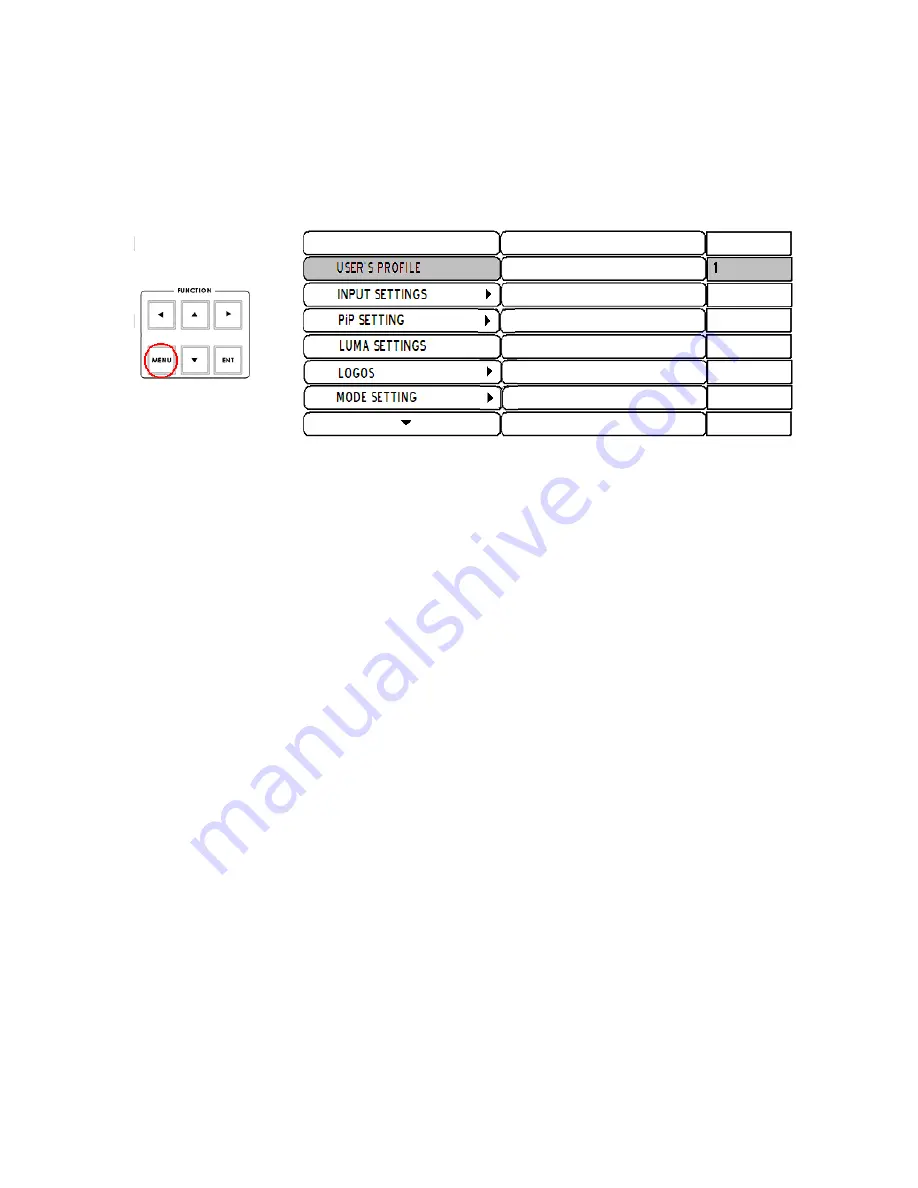
Menu and Navigation 

 
Press the 

MENU

 button in the 

Function

 section of the HS-2000L’s keyboard to enter the 

System Configuration Menu

The menu will be displayed on the HS-2000L’s Multi Preview output as below.  
 
Press the 

UP

DOWN

,

 LEFT

 and 

RIGHT

 arrow buttons to highlight or select a menu option. Then use the 

UP

 and 

DOWN

 arrow buttons to change the value of the selected item or option. Press the 

ENT 

button


to 

Enter

 and save your 

chosen value for the selected menu item.  


USER’S PROFILE 

Press the 

MENU

 button and highlight the 

USER’S PROFILE 

option.  

Press the arrow 

RIGHT

 button and select a profile number by using the 

UP

 and 

DOWN

 arrows. 

Press the 

ENT

 button to confirm the chosen profile number to be used. 

The current user will also be confirmed between PREVIEW and PROGRAM windows on the Multi Preview 
Display. 

Up to 6 User Profiles can be configured and saved. These profiles are numbered 0 ~ 5.


User’s Profile 0

 is also referred to as the 

BASIC or MASTER USER 

settings profile. 


If there are settings that will be common to all user profiles 1 ~ 5 then they are set here first under BASIC and 
then these common settings can be copied to the other user profiles (1 ~ 5) by selecting LINK TO BASIC

. Then 

while adjusting USER 1 ~ 5, you can refer to the 

BASIC

 settings, thus avoiding multiple and repeated 

adjustments for all remaining user profiles. 

Any changes made to the HS-2000L’s configuration will be saved to the currently selected profile.


The default user profile at Power On is the last selected profile used.  


INPUT SETTINGS  

Press the 

MENU

 button and highlight the

 INPUT SETTINGS 

option. 

Press the arrow buttons to select an item and press the 

ENT

 to confirm the setting. 

BRIGHTNESS: 

adjustment range from -7 to +7 

CONTRAST:

 adjustment range from -7 to +7 

SATURATION: 

adjustment range from -7 to +7 

MASTER USER SETTING:

 When selected, the values for the above are copied from the 

BASIC

 profile.


Содержание HS-2000L

Страница 1: ......

Страница 2: ...n Menu 11 Audio Inputs and Levels 15 HS 2000L Configuration Utility 16 Storing New Logos 16 Setting up a Luma Key overlay with Power Point 17 HD SDI Cabling Advice 18 Intercom Monitor Control Panel 19...

Страница 3: ...Datavideo within 30 days of purchase For information on how to register please visit www datavideo tek com or contact your local Datavideo office or authorized Distributors Certain parts with limited...

Страница 4: ...RCOM MIXER 13 Headphone MIC Headphone Socket Intercom 14 Headphone Socket Monitor 15 Headphone Volume Control 8 12 9 7 6 3 5 1 2 1 Audio input selectors Level Controls 2 Audio meters 3 Menu and Contro...

Страница 5: ...dphone section to accurately monitor any of the sources CH1 CH 2 CH3 CH4 or Master output Repeated presses of the Headphone Audio Monitor button will cycle through the monitoring choices In many cases...

Страница 6: ...the selected main and sub sources The selected sub source becomes the main program output with no transition effect applied TAKE Starts an automated switch between the main and sub sources The select...

Страница 7: ...decrease rather than increase the signal levels to create a balanced and pleasing mix When the CH1 CH4 Audio Level Faders are set at 6dB or Unity they pass the audio signal through at the same level a...

Страница 8: ...to use for more information see INPUT 4 MODE DVI D IN DVI I Signal Input Digital Input 5 RS 232 9 pin serial port standard RS 232 interface Connect PC to update firmware Logos or Mixer Configuration 1...

Страница 9: ...Supports two channels XLR Balanced Audio output TO BELTPACK For Intercom Channel Input Output XLR Sockets Each of the 5 channels has an XLR connector that carries bi directional signals between the I...

Страница 10: ...of the transition controls and provides the Sub Source video for Picture in Picture and Key functions Transition Effects WIPE from upper Left corner to lower Right corner of screen WIPE from Left to...

Страница 11: ...Profiles can be configured and saved These profiles are numbered 0 5 User s Profile 0 is also referred to as the BASIC or MASTER USER settings profile If there are settings that will be common to all...

Страница 12: ...ght the LUMA SETTING option Press the arrow buttons to select an item and press the ENT to confirm the setting You can set the value for the LUMA LEVEL 0 Black to 255 White This LUMA LEVEL keys out a...

Страница 13: ...sa MASTER USER SETTING When selected the values for the above are copied from the BASIC profile The changed setting will also be confirmed between PREVIEW and PROGRAM windows on the Multi Preview Disp...

Страница 14: ...TINGS Press the MENU button and highlight the FACTORY SETTINGS option Press the arrow buttons to select an item and press the ENT to confirm the setting This menu option is used when it is required to...

Страница 15: ...ve the audio follows the video through a transition This means that when this LED is lit only one channel of the Audio input section CH1 CH2 CH3 CH4 can be activated at a time When the transition is a...

Страница 16: ...reen will be displayed as above when the program is launched Storing New Logos The Configuration Utility software allows a Windows XP Professional PC to make changes to the Logos stored within the 14...

Страница 17: ...cannot see the PC s output extend the PC s desktop within Windows to monitor 2 as below 5 PC screen size for monitor 2 should match the HD resolution for example 1920x1080 or 1280x720 6 If DVI VTR2 is...

Страница 18: ...h a tipping point and this will bring about a total loss of picture also known as the Cliff Effect Always check with your supplier for cabling advice on the maximum distance for a particular signal an...

Страница 19: ...e active at any given time active channels are illuminated red All active channels will hear any communication from the operator or from any other active channel The buttons will also indicate if any...

Страница 20: ...MI source input of Rear Panel It s a full screen display When you push the PREVIEW button then you go back to show multi view from the other SDI inputs So you can switch back forth between HDMI Previe...

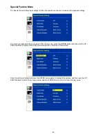
Страница 21: ...M 170 is set up via on screen menus To display the on screen menu press the MENU button The menus are navigated using the Up Down buttons There are four menus Colour Processor PIP Feature Setting Spec...

Страница 22: ...hlighted To adjust the Brightness press Enter again An adjustment bar will appear at the bottom of the screen Use the Up Down buttons to change the setting and then press Enter to store the new value...

Страница 23: ...e picture in picture The position size main source and sub source can be set in the menus To access the menu press enter so that PIP Mode is highlighted To access the options for the selected setting...

Страница 24: ...CVBS 1 CVBS 2 SVIDEO COMP Component HDMI SDI PIP Sub Source CVBS 1 CVBS 2 SVIDEO COMP Component HDMI SDI N B The PIP feature can only be one analogue source and one digital source i e If the main sou...

Страница 25: ...e same way as the other menus press the ENTER button and then use the UP DOWN buttons to highlight the setting you want to alter In this case Frame Ratio Once the setting is highlighted press the ENTE...

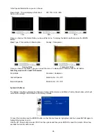
Страница 26: ...utton N B Only works in 16 9 and 16 10 modes Scan Mode Overscan Underscan Internal Speaker Mute Control On Off External Speaker Mute Control On Off System Info Menu The System Info Menu displays the F...

Страница 27: ...olor Tally LED Will illuminate RED when the channel is LIVE and AMBER when the channel is CUED Talk Button Opens up talk back communication with the ITC 50 base station and any other active channels P...

Страница 28: ...convenient place such as on top of the camera When the channel is LIVE the LED will be RED and when the channel is CUED the LED will be AMBER N B The Tally LED on the ITC 100SL will continue to operat...

Страница 29: ...to 1 5 GHz Output level 0 8 Vpp 10 Rise time Less than 270 ps Fall time Less than 270 ps Difference between rise time and fall time within 100 ps Alignment jitter Less than 0 2 UI Timing jitter Less...

Страница 30: ...dset Impedance 8 600 ohms 100mW min Microphone Level 67Db or 2 5mm Stereo Jack Socket for Motorola Mobile Phone type headset microphone TALLY OUT SOCKET 3 5mm Jack Socket to connect to TD 2 Tally Indi...

Страница 31: ...31 Notes...

Страница 32: ...32...

Отзывы: