background image


10

5. Place the lid on top of the Enclosure.  Make sure the two copper screw 

holes are aligned with Front View.  Firmly push the lid down from back to 
front and lock the lid on the Enclosure.  Make sure the lid is securely in 
place. 


6. Find the two smaller Case screws enclosed inside the package and fasten 

two Case screws to attach the lid onto the Enclosure (Front View). 


Содержание FireWire 400

Страница 1: ...1 Rev 01...

Страница 2: ...5 SYSTEM REQUIREMENT 6 PC 6 MAC 6 PACKAGE CONTENTS 6 SYSTEM UNIT VIEWS 7 FRONT VIEW 7 ASSEMBLING THE SATA 2 5 HDD ENCLOSURE 8 CONNECTING THE ENCLOSURE KIT TO A COMPUTER 11 SAFE REMOVAL OF THE UNIT 12...

Страница 3: ...terference This device must accept any interference received including interference that may cause undesired operation This equipment has been tested and found to comply with the limits for a Class B...

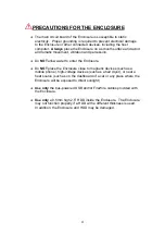
Страница 4: ...NOT allow water to enter the Enclosure Do NOT place the Enclosure close to magnetic devices such as a mobile phone high voltage devices such as a hair dryer or near a heat source such as on the dashb...

Страница 5: ...ase thoroughly read and follow the instructions provided in this manual Failure to do so may result in damage to the Enclosure and any or all of the connected devices Features Supports current SATA II...

Страница 6: ...r Mac OS X 10 4 Mac OS 9 0X or higher PowerPC or Mac OS X 10 4 or higher Intel One available USB 2 0 IEEE 1394a or IEEE 1394b port upon model 2 5 inch SATA compatible hard drive is required for the En...

Страница 7: ...7 SYSTEM UNIT VIEWS Front View AU S10 USB Mini B port Case Screws AT S111 USB Mini B port Case Screws FireWire 400 Port FireWire 800 Port...

Страница 8: ...nt to back and open the Enclosure After the lid is opened the PCBA board Printed Circuit Board should be securely in place inside the Enclosure One package containing the two HDD screws and two case s...

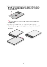
Страница 9: ...ing that the hard drive and PCBA alignment is properly maintained The smaller Case screws are for fastening the Enclosure s housing and lid together 4 Carefully align the PCBA board with the hard driv...

Страница 10: ...re aligned with Front View Firmly push the lid down from back to front and lock the lid on the Enclosure Make sure the lid is securely in place 6 Find the two smaller Case screws enclosed inside the p...

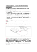
Страница 11: ...LED at the same place will flash in blue Now the enclosure kit is ready to be used The hidden LED on its top cover will indicate the power and data access statuses The Enclosure should only be connect...

Страница 12: ...EXTERNAL BOOTUP External Bootup may be required if the user has two different operating systems set up in both the host computer and the Enclosure PC The External Bootup with different interface OS In...

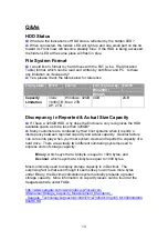
Страница 13: ...the HDD available space as to be less than 320GB A Many customers are confused by their host systems when it reports a discrepancy between reported capacity and actual capacity Several factors can co...

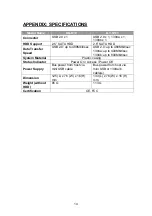
Страница 14: ...to 480Mbit sec USB 2 0 up to 480Mbit sec 1394a up to 400Mbit sec 1394b up to 800Mbit sec System Material Plastic casing Status Indicator Power On Access Power Off Power Supply Bus power from host via...

Отзывы: