C
HAPTER
9 E
XTEND
Y
OUR
P
ROGRAM
: Add an Alarm
63
UM-0071-A0
9-9
A
DD
AN
A
LARM
Here you assign an alarm to the potentiometer
channel.
Because alarm channels don’t generate data, you’ll
make a copy of the potentiometer channel and assign
the alarm to the copy. In this way, the original instance
of the potentiometer channel generates data, and the
copy generates alarms.
➲
Add an alarm that triggers when the
potentiometer’s resistance is greater than 300
ohms.
To do this…
a) Turn the potentiometer knob fully
anti
-clockwise
(minimum resistance).
b) In the View menu, make sure that
Show Alarm
Events
is ticked.
This ensures that DeLogger will automatically open
the Event Logs dialog box (Figure 34 on page 36)
when an alarm occurs.
c) Click the text window to make it active. In the Text
menu, choose
Display Screen
>
Display Data As…
then select
Replay format
and click
OK
.
In this format, alarms are obvious in the text
window’s display screen.
d) Click the program builder window to make it active.
e) On tab A of the program builder, use the right-
button copy and paste method (see Figure 57 on
page 57) to copy row 1 to row 5.
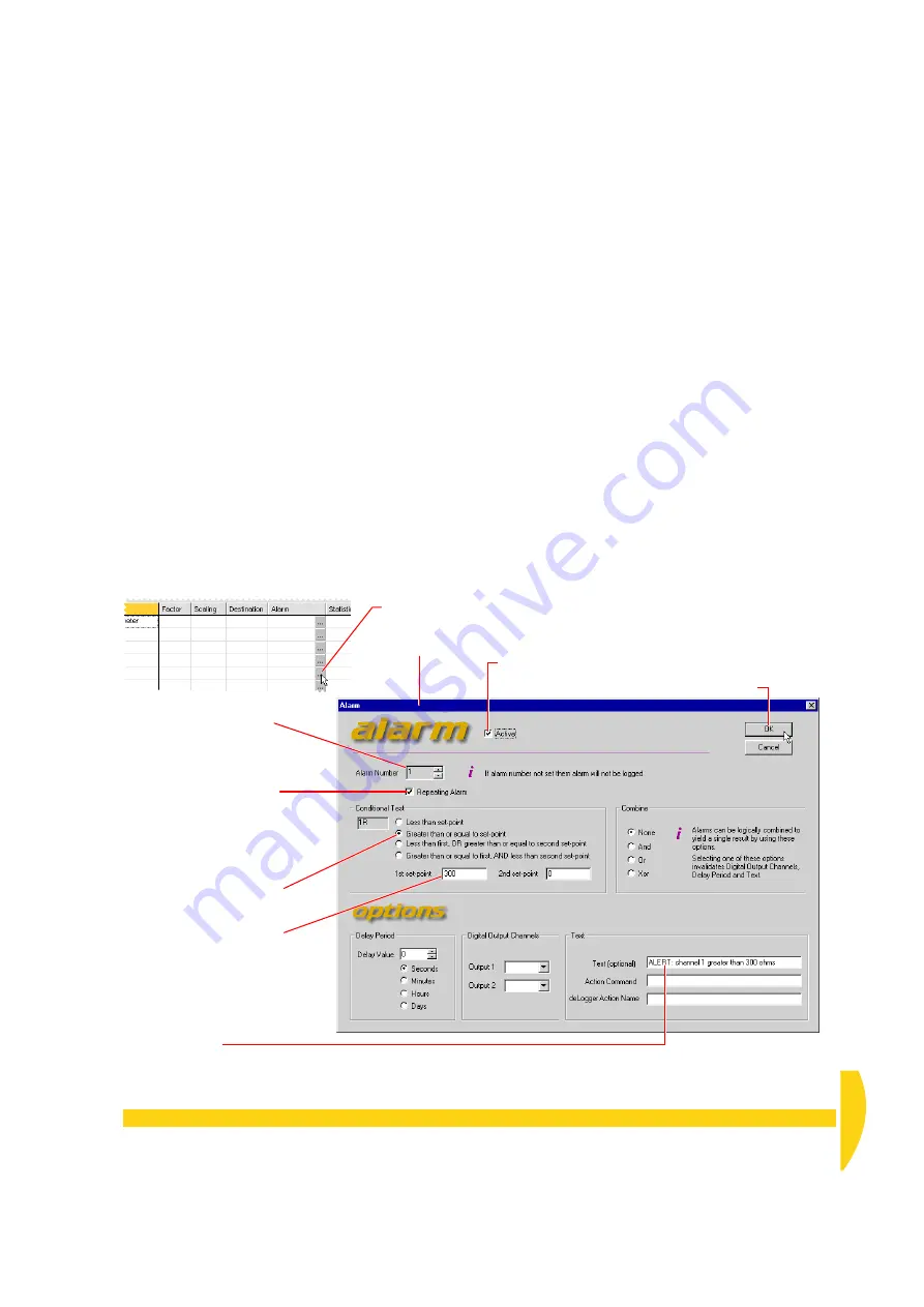
f) Follow the numbered steps in Figure 65 to specify
the alarm for row 5.
g) In DeLogger’s File menu, choose
Save Project
.
h) In the Program menu, choose
Send to Connection
.
Click
Yes
or
OK
in any
Warning
or
Attention
dialog
boxes that open.
➊
Click the Configure button in
R5
’s
Alarm
column.
The Alarm
dialog box
opens.
➋
Tick
Active
.
➐
Click
OK
.
➍
Tick
Repeating Alarm
to have the DT800 return
an alarm event on every
scan while the alarm
condition exists (not just on
the first alarm scan).
➌
Set Alarm Number to
1
.
➍
Select the
Greater than
or equal to…
option.
➎
Type
300
in the 1st set-
point field.
➏
Type an alarm message in
the
Text
field
.
F
IGURE
65
Specifying an alarm for channel 1
Содержание DT800
Страница 1: ...UM 0071 A0 ...
Страница 2: ...UM 0071 A0 ...
Страница 73: ...UM 0071 A0 ...
Страница 74: ...UM 0071 A0 ...


