background image

DI–4718B Series Hardware Manual

Instrument Controls, Indicators, and Connections

11

9. After all modules are installed and indicated on the sticker reassemble the instrument making sure not to over-

tighten the front screws. 

Note: If your are installing a thermocouple module you must enable the Cold Junction 

Compensation jumper for that channel (see “Enabling CJC for Thermocouple Modules” section below for more 
information).

Enabling CJC for Thermocouple Modules

Enable Cold Junction Compensation for each Thermocouple Input module installed. The CJC Enable Jumpers are 
located on the circuit board of the instrument. 

Note: If you are not using a Thermocouple Input Module on that chan-

nel be sure the jumper is disabled (removed or installed on only one pin) because this will affect the input signal. 

Each channel has its own CJC enable jumper located in front of each channel position on the instrument circuit board. 

1. Unplug the device and make sure there is no power to the instrument.

2. Remove the front panel and bezel by removing the two screws on the front of the instrument.

3. Remove the ground lug from the back of the instrument.

4. Pull the circuit board apart from the casing to reveal the CJC Enable Jumpers.

5. Install a jumper onto the board for each channel that uses a thermocouple module. Eight jumpers are provided 

with the DI-4718B for this purpose.

Note: If you are not using a Thermocouple Input Module on that channel be sure the jumper is disabled (removed 
or installed on only one pin) because this will affect the input signal.

6. After the DI-8B modules and jumpers are installed reassemble the instrument making sure not to overtighten the 

two front screws.

CHANNEL   8 

CHANNEL   5 

CHANNEL   4 

CHANNEL   1 

CHANNEL   2 

CHANNEL   3 

CHANNEL   6 

CHANNEL   7 

CJC Enable Jumpers 

Circuit Board with DI-8B Backplane 

Casing 

Front of DI-4718B

Содержание DI-4718B

Страница 1: ...al or otherwise without expressed written authorization from the com pany The distribution of this material outside the company may occur only as authorized by the company in writing DATAQ Instruments...

Страница 2: ......

Страница 3: ...products that have been repaired or altered by persons other than DATAQ Instru ments employees or products that have been subjected to misuse neglect improper installation or accident DATAQ Instrumen...

Страница 4: ......

Страница 5: ...12 Low pass Filter 12 Resolution as a Function of Sample Rate 13 Built In Remote Control Jack 14 WinDaq Remote Events 14 WinDaq Remote Storage 15 General Purpose Digital Inputs 15 Instrument Rear Pane...

Страница 6: ...Wire RTD Input Modules 32 DI 8B35 Linearized 4 Wire RTD Input Modules 33 DI 8B36 Potentiometer Input Modules 34 DI 8B38 Strain Gage Input Modules Narrow Wide Bandwidth 35 DI 8B40 41 Analog Voltage In...

Страница 7: ...ssion through their PC then record data in the field to removable flash memory via the USB drive port without being connected to their PC ChannelStretch not supported in stand alone mode Stand alone d...

Страница 8: ...creen It operates displays and records data in real time when connected to your PC An optional unlock code is available to sync multiple units into a single WinDaq file WINDAQ Waveform Browser playbac...

Страница 9: ...r sampling Stand alone None CJC Error 1 5 C plus 8B Module Isolation via DI 8B Modules Input to Output 1000VDC Peak AC Channel to Channel 500VDC Peak AC Digital Inputs Ports 2 Maximum drain voltage 25...

Страница 10: ...for status indication Power Connector USB 9 to 36 VDC 2 watts 8B modules Ethernet 9 to 36 VDC 2 5 watts 8B modules Ethernet Connector RJ45 Optional PoE Front Panel Connections Input connectors Two rem...

Страница 11: ...ating Temperature 0 C to 50 C 32 F to 122 F Operating Humidity 0 to 90 non condensing Storage Temperature 20 C to 60 C 4 F to 140 F Storage Humidity 0 to 90 non condensing Physical Characteristics Enc...

Страница 12: ......

Страница 13: ...l packing material in the unlikely event that your unit must for any reason be sent back to DATAQ Instruments Install WINDAQ Software and the WinDaq Dashboard All software for the DI 4718B can be inst...

Страница 14: ...d apply power All DI 4718B versions can be connected to your com puter s USB port using the provided USB cable for configuration Ethernet models can also be connected to your computer anywhere on your...

Страница 15: ...Connections The two 16 port screw terminals on the front of the instrument are used to interface analog input channels 1 through 8 Each channel has four terminals In In Ex and Ex for input signals and...

Страница 16: ...uit board apart from the casing to reveal the DI 8B backplane 7 Plug the DI 8B module firmly into one of the channel positions clearly labelled on the backplane and secure with the set screw DI 8B mod...

Страница 17: ...own CJC enable jumper located in front of each channel position on the instrument circuit board 1 Unplug the device and make sure there is no power to the instrument 2 Remove the front panel and beze...

Страница 18: ...the pressure flap tightens only against the signal wire and not the wire insulation Do not over tighten 3 Tug gently on the signal lead to ensure that it is firmly secured When an input signal is con...

Страница 19: ...cy are permanently disabled for the DI 4718B as are Input Types Nonlinear and Thermocouple and selections for Unipolar and Fahrenheit Resolution as a Function of Sample Rate The resolution of the DI 4...

Страница 20: ...ents Once the switch closure or TTL signal is connected activate Remote Events through WINDAQ Acquisition Software Events may be automatically placed on the rising or falling edge of the trigger signa...

Страница 21: ...on the rising or falling edge of the trigger signal Use the menu command Options Remote Storage 1 to set WINDAQ to begin recording on low to high transitions of the Record input Use the menu command O...

Страница 22: ...rt allows you to connect the instrument to your PC via Ethernet cable When in Ethernet mode the USB connection is inactive Mini B USB Port The Interface port allows you to connect the instrument to yo...

Страница 23: ...rument is in Error mode mode LED is solid red some action must be taken to fix the error before you can use it Generally the Control But ton can be used to make the instrument operational again when i...

Страница 24: ...configuration 1 Save configuration files to your USB thumb drive 2 Confirm device is in Idle mode for USB Flash Drive mode LED blinks Green Yellow 3 Push and hold the Control button 4 Plug the thumb d...

Страница 25: ...uiring data and waiting for a trigger condition to begin recording to your USB thumb drive Do not remove power or the USB thumb drive either could result in data file corruption Blinking Blue Cyan Re...

Страница 26: ...settings configure your instrument for stand alone data logging to record data to a USB flash drive and access the USB thumb drive via the Ethernet interface Devices in a ChannelStretch Group can syn...

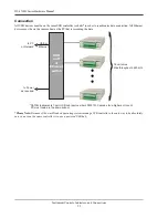
Страница 27: ...other USB devices via the USB interface The DI 4718B E can also synchronize with other Ethernet instruments via the Ethernet interface Connect up to 16 DI 4718B DI 1120 DI 4108 and or DI 4208 devices...

Страница 28: ...as the PC that is recording the data Please Note Because of the way Windows operating systems manage USB controllers the only way to be absolutely sure you are on the same controller is to use a power...

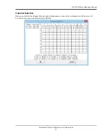
Страница 29: ...l Instrument Controls Indicators and Connections 23 Channel Selection Devices are listed in the Channel Selection grid in alpha numeric order of the serial numbers of the device All devices must be co...

Страница 30: ......

Страница 31: ...ed Go to https www dataq com products di 4718b di 4718b u html or https www dataq com products di 4718b di 4718b e html to purchase the unlock code under Accessories or call 330 668 1444 Once purchase...

Страница 32: ......

Страница 33: ...DI 4718B Series Hardware Manual Dimensional Drawing 27 6 Dimensional Drawing SIDE VIEW 0 750 1 125 1 000 4 000 5 000 0 230 5 230 0 120 4 40 MOUNTING HOLE 4 PLACES FRONT VIEW 1 485 4 140...

Страница 34: ...DI 4718B Series Hardware Manual Dimensional Drawing 28...

Страница 35: ...anti aliasing and the other two are on the system side A special input circuit on the DI 8B30 and DI 8B31 modules provides protection against accidental connection of power line voltages up to 240VAC...

Страница 36: ...frequency response which provides 70dB of normal mode rejection at 60Hz One pole of this filter is on the field side of the isolation barrier for anti aliasing and the other two are on the system sid...

Страница 37: ...then chopped by a proprietary chopper circuit and transferred across the transformer isolation barrier suppressing transmission of common mode spikes and surges The computer side circuitry reconstruc...

Страница 38: ...a three pole filter optimized for time and frequency response which provides 70dB of normal mode rejection at 60Hz One pole of this filter is on the field side of the isolation barrier for anti alias...

Страница 39: ...tion current does not flow in the input signal leads which allows RTD measurements to be made independent of lead resistance The excitation cur rents are small 0 25mA which minimizes self heating of t...

Страница 40: ...self heating of the potentiometer Signal filtering is accomplished with a three pole filter optimized for time and frequency response which provides 70dB of normal mode rejection at 60Hz One pole of...

Страница 41: ...e of the isolation barrier for anti aliasing and the other four are on the system side A special input circuit on the DI 8B38 module provides protection against accidental connection of power line vol...

Страница 42: ...system side A special input circuit on the DI 8B40 and DI 8B41 modules provides protection against accidental connection of power line voltages up to 240VAC Clamp Circuits on the I O and power termin...

Страница 43: ...se which provides 60dB per decade of normal mode rejection above 100Hz One pole of this filter is on the field side of the isolation barrier for anti aliasing and the other two are on the system side...

Страница 44: ...r for anti aliasing and the other four are on the system side A special input circuit on the 8B43 modules provides protection against accidental connection of power line voltages up to 240VAC Clamp ci...

Страница 45: ...rs The excitation is available on the EXC terminal with return on the terminal A special input circuit on the DI 8B45 modules provides protection against accidental connection of power line volt ages...

Страница 46: ...mode rejection at 60Hz One pole of this filter is on the field side of the isolation barrier for anti aliasing and the other two are on the system side A special input circuit on the DI 8B47 module pr...

Страница 47: ...e system side A special input circuit on the DI 8B50 and DI 8B51 modules provides protection against accidental connection of power line voltages up to 240VAC Clamp circuits on the I O and power termi...

Страница 48: ......

Отзывы: