


Serial BootBar v.090212d
Page 7
Installation
Rack Mounting
The iBootBar is designed for mounting in a standard 19” equipment cabinet.
1. There are two L-shape brackets marked as “L” and “R”, install the “L” bracket on the left side of the sBB chassis then
the “R” bracket on its right side.
2. Install the sBB to the standard 19-inch rack.
Serial Port
The iBootBar has a 9 pin D subminiature connector for RS-232 serial control. The connector is configured as DCE for
direct connection to a laptop or other terminal device. Default serial parameters are 115,200 bps, 8 data, no parity, 1 stop
bit (115200,8,n,1).
Serial Port pinout:
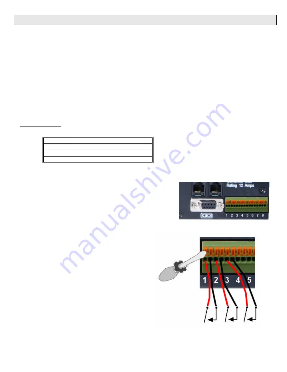
Control Inputs
Serial Boot Bars have 16 terminal block connections for control of individual
outlets using contact closure / contact open connections. Each connection
marked 1 through 8 controls the outlet of the same number. The remaining
8 connections are ground, and are interchangeable. Using a small flat-
blade screwdriver, depress the wire release mechanism for one of the
terminals on the terminal block and insert the bare wire into the terminal.
Remove the screwdriver to secure the wire. Gently tug on the wire to verify
that it is secure in the terminal block.
The default setting for the sBB is:
Contact Open = Power On
Contact Closed = Power Off
This setting is changeable through the serial port.
Caution:
Use only dry switch or relay closures, or open
collector relay drivers to connect to the sBB inputs. If you
have any doubts about proper connections, consult Dataprobe
Technical support.
Pin No
Description
2
Receive Data
3
Transmit Data
5
Signal Ground
Depress release to insert or remove wire


