background image

Introduction

The Datapath range of expansion chassis are solutions that allow system builders and integrators the  

flexibility to extend a PCIe based PC or motherboard enabling a larger, distributed system architecture.  

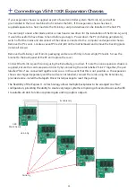
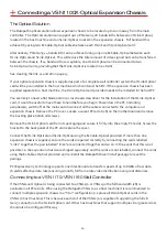
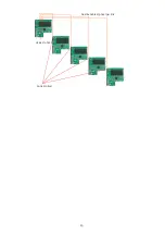
The optical expansion chassis can be used to create systems with distances of up to 100m between the 
host PC and the expansion chassis.

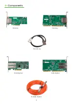
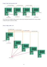
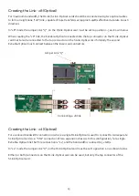
The expansion link is created using a combination of Host Link (HLink) and Slave Link (SLink) cards  
connected together using a cable or a series of cables (copper or optical), these combined provide a high 
bandwidth PCI Express link from an upstream host to a distributed expansion unit.  

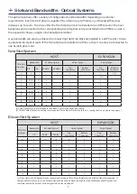
Expansion Chassis Models

Backplane

Number of Available PCIe Slots

VSN900X

Express9-G3 (SLink-G3 installed)

9

VSN1100X

Express11-G3 (SLink-G3 installed)

11

VSN900X-Optical 

Express9-G3 (SLink-Optical installed)

9

VSN1100X-Optical

Express11-G3 (SLink-Optical installed)

11

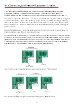
Connecting multiple expansion chassis vastly increases the number of available PCI Express slots capable 
of running large, complex video walls supporting high bandwidth and low latency video capture.  
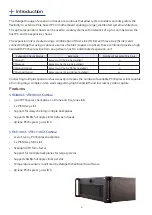
Features

VSN900X/VSN900X-Optical

• 

9 slot PCI Express backplane 1 x 8 lane and 8 x4 lane slots

• 

1 x PICMG 1.3 slot

• 

Support for daisy chaining multiple backplanes

• 

Supports 8GB/s full duplex links between chassis.

• 

48 lane PCI Express 3.0 switch

 
VSN1100X/VSN1100X-Optical

• 

11 slot, Gen.3 PCI Express backplane

• 

1 x PICMG 1.3 SBC slot

• 

Standard ATX form factor

• 

Support for multiple backplanes for large systems

• 

Supports 8GB/s full duplex links per slot

• 

Temperature sensors monitored by Datapath Wall Monitor software

• 

96 lane PCI Express 3.0 switch

4

Содержание VSN900X

Страница 1: ...VSN900X VSN1100X Version 1 1 User Manual Expansion Chassis...

Страница 2: ...onnecting aVSN900X Expansion Chassis 8 Connecting aVSN900X Optical Expansion Chassis 9 Connecting aVSN1100X Expansion Chassis 11 Connecting aVSN1100X Optical ExpansionChassis 12 Inserting and Removing...

Страница 3: ...h Produkt undVerletzungen der Nutzer Bitte lesen Sie sie sorgf ltig durch bevor Sie Ihr Produkt in Betrieb nehmen Diese Anweisungen sollten allen Personen zug nglich gemacht werden die mit der Nutzung...

Страница 4: ...G3 SLink G3 installed 9 VSN1100X Express11 G3 SLink G3 installed 11 VSN900X Optical Express9 G3 SLink Optical installed 9 VSN1100X Optical Express11 G3 SLink Optical installed 11 Connecting multiple...

Страница 5: ...Gen3 VSN900X Optical 9 slot expansion system providing 8 PCIe gen3 x4 slots 1 PCIe gen2 x8 slot 1 x8 PCIe Gen3 VSN1100X 11 slot expansion system providing 11 PCIe Gen3 x8 slots VSN1100X Optical 11 slo...

Страница 6: ...6 Components HLink G3 SLink G3 ExCable G3 HLink Optical SLink Optical ExCable Optical...

Страница 7: ...nector Top Connector Bottom Connector 1 x x x x x x 1 1 x x x x 2 2 N A x x x x 3 N A x x x x 4 N A x x x x 5 N A x x x x 6 N A x x x x 7 N A x x x x 8 N A x x x x 9 N A x x x x 1 SLink Optical card i...

Страница 8: ...ll screws Remove the HLink G3 card from its packaging and secure it firmly into the empty PCIe slot Screw the bracket to the back panel of the PC and replace the cover Connect the HLink G3 and SLink G...

Страница 9: ...sis Remove the PC cover Locate a vacant PCIe slot x8 on the motherboard and remove the backing plate retain all screws Remove the HLink Optical card from its packaging and secure it firmly into the em...

Страница 10: ...al 2 x ExCable Optical 2 x ExCable Optical 2 x ExCable Optical 10 This is the recommended configuration for achieving the highest bandwidth when using multiple VSN900X Optical expansion chassis Star C...

Страница 11: ...HLink G3 card from its packaging and secure it firmly into an empty PCIe slot Screw the bracket to the back panel of the PC and replace the cover Connect the HLink G3 and SLink G3 using the ExCable G...

Страница 12: ...nnect all the cables connected to the computer and expansion chassis Remove the PC cover Locate a vacant PCIe slot x8 on the motherboard and remove the backing plate retain all screws Remove the HLink...

Страница 13: ...13 HLink Optical SLink Optical Dual ExCable Optical per link...

Страница 14: ...ks the cable in place Failure to lock the connector in place can result in the ExCable Optical becoming separated from the card and the link between chassis being lost Inserting and Removing the ExCab...

Страница 15: ...ctor on the SLink Optical card Similarly the second ExCable Optical must connect between the lower card connectors Jumper Link J7 Connecting a x8 link Creating the Link x4 Optical For a reduced bandwi...

Страница 16: ...ame locking It is assumed that displays controlled from the expansion chassis would be sufficiently far away from the host machine that this will not be a problem It should be noted that all displays...

Страница 17: ...ully inserted into the card until a definite click can be felt This locks the cable in place Failure to lock the connector in place can result in the ExCable G3 becoming separated from the card and th...

Страница 18: ...DegF StorageTemperature 20 to 70 DegC 4 158 DegF Relative Humidity 5 to 90 non condensing Noise 48 6dB A upto 67 9dB A Dependent on system configuration ambient temperature DIMENSIONS Length 500mm inc...

Страница 19: ...ath Web Site usually with a response within 24 hours excluding weekends Via Email Send an email to support datapath co uk with as much information about your system as possible To enable a swift respo...

Страница 20: ...xpress11 G3 11 F Features 4 Frame locking 16 H HLink G3 6 HLink Optical 6 Host PC 8 I Inserting the cable 17 20 Index Installing the HLink G3 card 11 Installing the HLink Optical 12 J Jumper Link J7 1...

Отзывы: