background image


H) 

Connect and secure the 

Interface Cable


to 

J2

 on the 

Cutter CCA

, and connect the 

Control Cable

 to 

J1

.


Interface

Cable

Cutter

CCA

Control

Cable

J2

J1

Rear Bracket


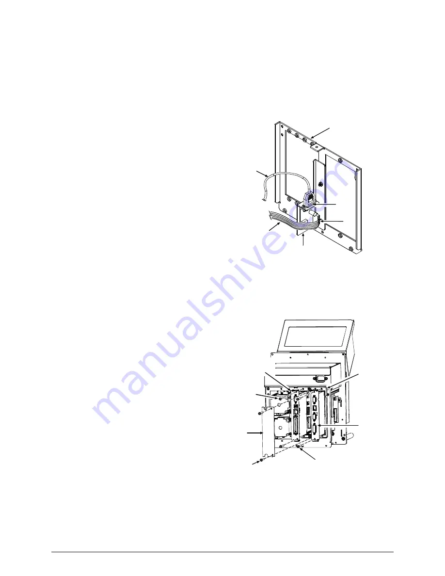
I) 

Replace the 

Card Cage

 items: 


 Replace 

the 

Main Logic CCA 

then secure 

it using the two 

Main Logic CCA Screws


 Replace 

the 

Applicator Interface CCA


then secure it using the two

 Applicator 

Interface CCA Screws

; and,  


 Replace 

the 

Card Cage Cover

 then 

secure it using the two 

Card Cage Cover 

Screws


Card

Cage

Applicator

Interface

CCA

Main Logic

CCA Screws

(2 places)

Applicator Interface

CCA Screws

(2 places)

Card

Cage Cover

Card Cage

Cover Screws

(2 places)

Main Logic

CCA


Содержание A Class Mark II

Страница 1: ...92 2534 01 Rev A Cutter Option Installation Instructions ...

Страница 2: ......

Страница 3: ...ower and unplug the power cord before starting this installation and when performing service Contents of the Cutter Kit This kit contains the following items 1 Mounting Bracket 2 Cutter CCA 3 Lock Washer 2 4 Jack Screw 2 5 Control Cable 6 Interface Cable 7 Screw 2 Flat Head M4 X 6 8 Cutter Assembly 9 Flat Washer 5 10 Screw 4 M4 X 20 11 Screw M4 X 10 12 Warning Label 5 9 7 6 3 1 2 4 8 WARNING 11 12...

Страница 4: ...ers the Cable Receiver in the Access Cover remove the Warning Label For the Cable Receiver s location see the illustration in Step 2 part C Warning Label Access Cover D Remove the following items from the Card Cage Remove the two Card Cage Cover Screws then remove the Card Cage Cover Remove the two Main Logic CCA Screws then remove the Main Logic CCA and Remove the two Applicator Interface CCA Scr...

Страница 5: ...acket removed for clarity It is not nessacry to remove the Rear Bracket from your printer A Starting from the back of the printer insert the Interface Cable Item 6 through the Centerplate Aperture B Connect the Control Cable Item 5 to J17 on the Backplane CCA Centerplate Aperture Interface Cable J17 Backplane CCA Control Cable C Snap the Interface Cable Connector securely into the Cable Receiver i...

Страница 6: ...rol Cable Drive Motor Cable Bundle F Place the Cutter CCA Item 2 into the Mounting Bracket Item 1 then install the Lock Washers Item 3 and Jack Screws Item 4 as shown Securely tighten the Jack Screws Cutter CCA Mounting Bracket Jack Screws Lock Washers G Secure the assembled Mounting Bracket to the Rear Bracket using the Mounting Screws Item 7 Rear Bracket Mounting Screws Mounting Bracket assemble...

Страница 7: ...Logic CCA then secure it using the two Main Logic CCA Screws Replace the Applicator Interface CCA then secure it using the two Applicator Interface CCA Screws and Replace the Card Cage Cover then secure it using the two Card Cage Cover Screws Card Cage Applicator Interface CCA Main Logic CCA Screws 2 places Applicator Interface CCA Screws 2 places Card Cage Cover Card Cage Cover Screws 2 places Ma...

Страница 8: ...vice Panel Rear Cover Service Panel Screws 2 places Rear Cover Screws 7 places L Align the Cutter Assembly Item 8 to the holes in the Centerplate and install the four Washers Item 9 and Long Mounting Screws Item 10 Also install the Washer Item 9 and Short Mounting Screw Item 11 However do not tighten these screws leave them loose enough to allow the Cutter Assembly to be positioned Cutter Assembly...

Страница 9: ...unting Screws Retighten the Vertical Mounting Screw Then tighten the Short Mounting Screw and the Thumbscrew Short Mounting Screw Cutter Assembly Cutter Throat Long Mounting Screw 4 places Lower Mounting Block Vertical Mounting Screw Thumbscrew N Connect the Cutter Cable to the Cutter Port and then affix the Warning Label Item 12 to the Cutter Assembly as shown O If removed from the applicator sys...

Страница 10: ... the Operator s Manual for loading details Then route the Media out the Cutter Opening B Plug the power cord into the AC Receptacle and turn On the Power Switch Cutter Throat Media C Ensure that READY is displayed on the front panel then press the FEED Key and proceed according to your observations y If a cut label is dispensed this completes the installation or y If the label feeds forward withou...

Страница 11: ...g program is properly configured for use and for cutting labels to the desired size To test the Cutter s operation see Testing the Cutter near the end of this document Maintaining the Cutter To ensure trouble free operation the Cutter should be cleaned after printing each roll of labels Additionally if the cutting action becomes sluggish immediate cleaning is recommended Clean the Cutter as follow...

Страница 12: ...uted for isopropyl alcohol provided this substitute is carefully and sparingly applied using a cotton swab Never spray WD 40 or a similar substance directly onto the assembly severe damage can result 5 While the Sled is raised check the Pad Wick for sufficient lubrication if dry replace the Pad Wick Pad Wick 6 Allow both blades to dry Replace the Cutter Cover and then secure it to the Cutter Assem...

Страница 13: ...unctional test of the Cutter A Press the MENU Key on the printer s front panel B Using the Key scroll to DIAGNOSTICS then press the ENTER Key C Using the Key scroll to OPTIONS TESTING then press the ENTER Key D Using the Key scroll to TEST CUTTER then press the ENTER Key E Using the Key or the Key select the number of test cycles 1 10 or 100 times that you want to perform F Press the ENTER Key to ...

Страница 14: ...able 3 shows the different basis weights for the differing media types which are equivalent in weight when compared to the metric weight Metric Weight to Thickness in Mils Metric Weight to Equivalent Weight in Lbs Metric Weight g m2 Copy Paper mils Business Card Stock mils Ticket Stock mils Label w Liner Stock mils Linerless label stock mils Metric Weight g m2 Basis Weight Copy Paper Basis Weight ...

Отзывы: